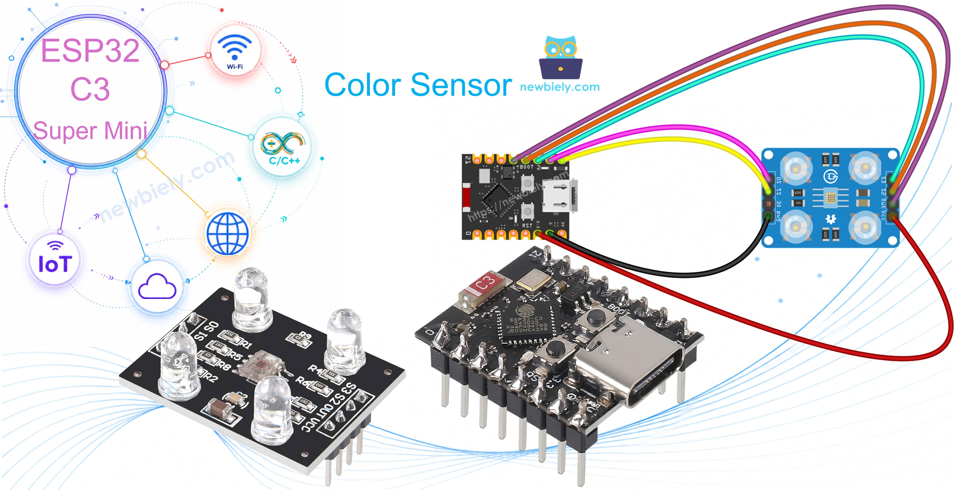
ESP32 C3 Super Mini TCS3200D/TCS230 색상 센서
ESP32 C3 Super Mini에 TCS3200D/TCS230 색상 센서를 연결하여 정확한 RGB 색상 감지를 수행하는 방법을 배웁니다. 이 초보자 친화적인 튜토리얼은 보정 및 실시간 색상 측정을 다룹니다.
배울 내용:
- TCS3200D/TCS230 색상 센서가 무엇이고 색상을 감지하는 방식
- TCS3200 센서를 ESP32 C3 Super Mini에 배선하는 방법
- 정확한 판독값을 위해 센서를 보정하는 방법
- RGB 색상 값을 읽고 표시하는 방법
- 색상 감지 프로젝트의 실제 응용 프로그램
필요한 하드웨어
| 1 | × | ESP32 C3 Super Mini | 아마존 | |
| 1 | × | USB 케이블 타입-A to 타입-C (USB-A PC용) | 쿠팡 | 아마존 | |
| 1 | × | USB 케이블 타입-C to 타입-C (USB-C PC용) | 아마존 | |
| 1 | × | TCS3200D/TCS230 Color Recognition Sensor Module | 아마존 | |
| 1 | × | 브레드보드 | 쿠팡 | 아마존 | |
| 1 | × | 점퍼케이블 | 쿠팡 | 아마존 |
공개: 이 포스팅 에 제공된 일부 링크는 아마존 제휴 링크입니다. 이 포스팅은 쿠팡 파트너스 활동의 일환으로, 이에 따른 일정액의 수수료를 제공받습니다.
TCS3200D/TCS230 색상 센서 정보
TCS3200D/TCS230은 특수한 포토다이오드 필터를 통해 빛 반사를 측정하여 색상을 감지하는 광학 센서입니다.
주요 특징:
- 8×8 배열의 64개 포토다이오드(16개의 빨강 필터, 16개의 녹색, 16개의 파랑, 16개의 투명)
- 광도에 비례하는 주파수 출력
- 작동 전압: 2.7V ~ 5.5V(5V 권장)
- 일관된 판독값을 위한 내장 흰색 LED 조명
- 출력 주파수 범위: 2Hz ~ 500kHz
- 초보자에게 이상적: 간단한 디지털 출력, 복잡한 아날로그 판독 불필요
유용한 이유:
- 온보드 LED 덕분에 다양한 조명 조건에서 작동
- ESP32 C3 Super Mini 디지털 핀과 쉽게 인터페이스 가능
- 색상 분류, 일치 및 감지 프로젝트에 완벽
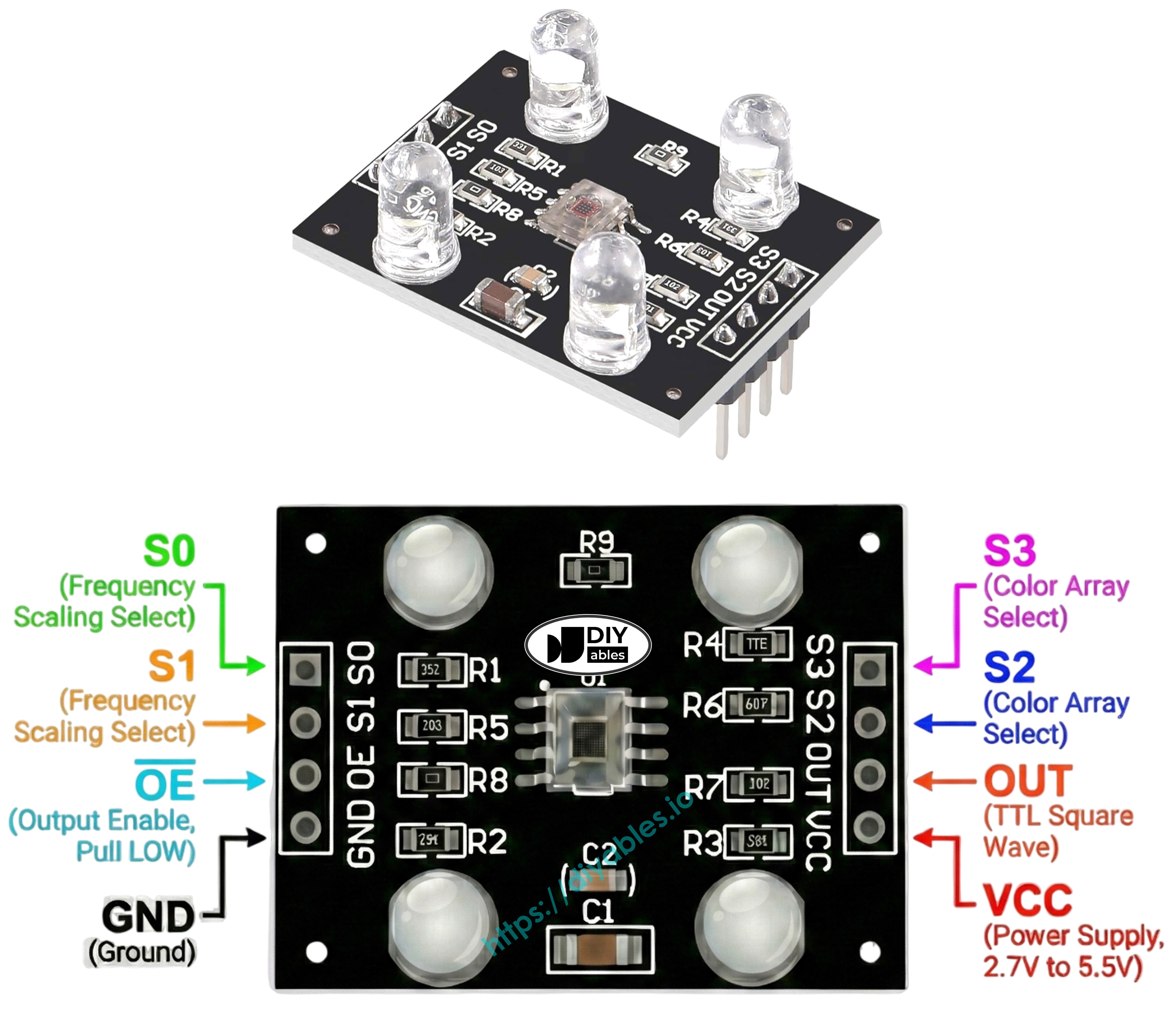
핀아웃
TCS3200D/TCS230 색상 센서는 8개의 연결 핀을 가지고 있습니다:
- VCC: 전원 공급 입력(5V에 연결)
- GND: 그라운드 연결(0V 기준)
- S0: 주파수 스케일링 제어 핀 1
- S1: 주파수 스케일링 제어 핀 2
- S2: 색상 필터 선택 핀 1
- S3: 색상 필터 선택 핀 2
- OUT: 주파수 출력 신호 핀(ESP32 디지털 핀에 연결)
- OE: 출력 활성화 핀(활성 LOW, 일반적으로 GND에 연결)
작동 원리
TCS3200 색상 센서는 두 가지 제어 시스템을 사용하여 작동합니다:
주파수 스케일링(S0 및 S1 핀):
- S0=LOW, S1=LOW: 전원 차단 모드
- S0=LOW, S1=HIGH: 2% 주파수 스케일링
- S0=HIGH, S1=LOW: 20% 주파수 스케일링
- S0=HIGH, S1=HIGH: 100% 주파수 스케일링(권장)
색상 필터 선택(S2 및 S3 핀):
- S2=LOW, S3=LOW: 빨강 필터 활성
- S2=LOW, S3=HIGH: 파랑 필터 활성
- S2=HIGH, S3=LOW: 투명 필터(필터링 없음)
- S2=HIGH, S3=HIGH: 녹색 필터 활성
판독값 작동:
- OUT 핀은 구형파 신호를 출력합니다
- 밝은 빛으로 주파수 증가(2Hz ~ 500kHz)
- ESP32 C3 Super Mini는 pulseIn()을 사용하여 펄스 폭 측정
- 더 짧은 펄스 = 더 밝은 빛 = 더 높은 색상 강도
- 보정은 펄스 폭을 표준 RGB 값(0-255)으로 변환합니다
측정 정밀도 극대화
정확한 TCS3200 색상 판독값을 위해 다음 팁을 따르세요:
- 센서 거리를 물체에서 1-3cm로 고정 유지
- 일관된 각도로 센서 배치(수직이 최적)
- 안정적인 조명을 위해 내장 흰색 LED 사용
- 가능하면 외부 광원에서 센서 차단
- 실제 작업 환경에서 보정 수행
- 최적의 결과를 위해 평평한 무광 표면에서 테스트
배선 다이어그램
다음 간단한 배선 구성에 따라 TCS3200D 색상 센서를 ESP32 C3 Super Mini에 연결하세요:
안전 참고:
- 참고: TCS3200 센서는 USB를 통해 전원이 공급될 때 ESP32 C3 Super Mini가 제공할 수 있는 5V 전력으로 가장 잘 작동합니다.
| TCS3200 Color Sensor | ESP32 C3 Super Mini |
|---|---|
| VCC | 5V |
| GND | GND |
| S0 | D4 |
| S1 | D3 |
| S2 | D6 |
| S3 | D5 |
| OUT | D7 |
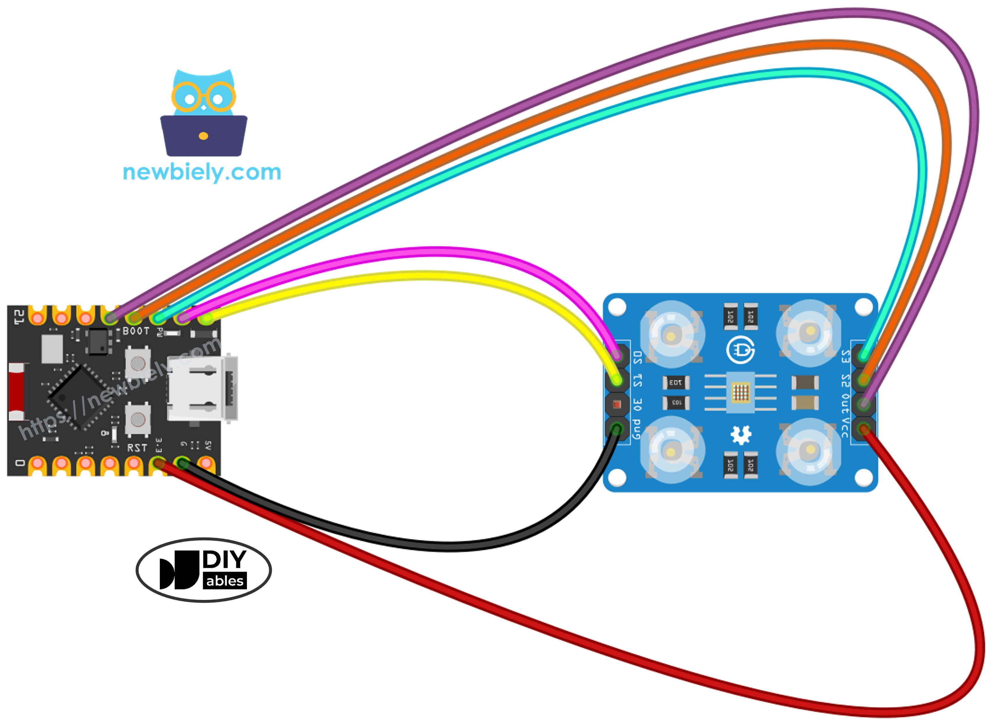
이 이미지는 Fritzing을 사용하여 만들어졌습니다. 이미지를 확대하려면 클릭하세요.
ESP32 C3 Super Mini 코드 - 센서 보정
특정 환경에 맞게 TCS3200 센서를 최적화하려면 이 보정 코드로 시작하세요.
이 코드가 하는 일:
- 완전한 주파수 스케일링(100%)으로 센서를 전원 켜기
- 빨강, 녹색 및 파랑 필터를 순환
- 각 색상의 최소 및 최대 펄스 폭 추적
- 다양한 색상을 표시할 때 보정 값을 지속적으로 업데이트
- 시리얼 모니터에 실시간 측정값 표시
/*
* 이 ESP32 C3 Super Mini 코드는 newbiely.kr 에서 개발되었습니다
* 이 ESP32 C3 Super Mini 코드는 어떠한 제한 없이 공개 사용을 위해 제공됩니다.
* 상세한 지침 및 연결도에 대해서는 다음을 방문하세요:
* https://newbiely.kr/tutorials/esp32-c3/esp32-c3-super-mini-tcs3200d-tcs230-color-sensor
*/
// Define color sensor pins
#define PIN_S0 4 // The ESP32 C3 SuperMini pin connected to the S0 of the color module
#define PIN_S1 3 // The ESP32 C3 SuperMini pin connected to the S1 of the color module
#define PIN_S2 6 // The ESP32 C3 SuperMini pin connected to the S2 of the color module
#define PIN_S3 5 // The ESP32 C3 SuperMini pin connected to the S3 of the color module
#define PIN_sensorOut 7 // The ESP32 C3 SuperMini pin connected to the OUT of the color module
// Variables for Color Pulse Width Measurements
int redPW = 0;
int greenPW = 0;
int bluePW = 0;
// Variables to track min and max pulse widths for calibration
int redMin = 10000, redMax = 0;
int greenMin = 10000, greenMax = 0;
int blueMin = 10000, blueMax = 0;
void setup() {
// Set S0 - S3 as outputs
pinMode(PIN_S0, OUTPUT);
pinMode(PIN_S1, OUTPUT);
pinMode(PIN_S2, OUTPUT);
pinMode(PIN_S3, OUTPUT);
// Set Pulse Width scaling to 20%
digitalWrite(PIN_S0, HIGH);
digitalWrite(PIN_S1, LOW);
// Set Sensor output as input
pinMode(PIN_sensorOut, INPUT);
// Setup Serial Monitor
Serial.begin(115200);
Serial.println("=== TCS3200 Calibration ===");
Serial.println("Point the sensor at different objects (white, black, colors).");
Serial.println("Min and Max values are tracked automatically.");
Serial.println("When values look stable, note them down for the next code.");
Serial.println("------------------------------------------");
}
void loop() {
// Read Red Pulse Width
redPW = getRedPW();
// Delay to stabilize sensor
delay(200);
// Read Green Pulse Width
greenPW = getGreenPW();
// Delay to stabilize sensor
delay(200);
// Read Blue Pulse Width
bluePW = getBluePW();
// Delay to stabilize sensor
delay(200);
// Update min and max values
if (redPW < redMin) redMin = redPW;
if (redPW > redMax) redMax = redPW;
if (greenPW < greenMin) greenMin = greenPW;
if (greenPW > greenMax) greenMax = greenPW;
if (bluePW < blueMin) blueMin = bluePW;
if (bluePW > blueMax) blueMax = bluePW;
// Print the pulse width values with min/max
Serial.print("Red PW = ");
Serial.print(redPW);
Serial.print(" - Green PW = ");
Serial.print(greenPW);
Serial.print(" - Blue PW = ");
Serial.println(bluePW);
Serial.print(" Min -> R:");
Serial.print(redMin);
Serial.print(" G:");
Serial.print(greenMin);
Serial.print(" B:");
Serial.println(blueMin);
Serial.print(" Max -> R:");
Serial.print(redMax);
Serial.print(" G:");
Serial.print(greenMax);
Serial.print(" B:");
Serial.println(blueMax);
Serial.println("------------------------------------------");
delay(1000);
}
// Function to read Red Pulse Widths
int getRedPW() {
// Set sensor to read Red only
digitalWrite(PIN_S2, LOW);
digitalWrite(PIN_S3, LOW);
// Read the Pulse Width
int PW = pulseIn(PIN_sensorOut, LOW);
// Return the value
return PW;
}
// Function to read Green Pulse Widths
int getGreenPW() {
// Set sensor to read Green only
digitalWrite(PIN_S2, HIGH);
digitalWrite(PIN_S3, HIGH);
// Read the Pulse Width
int PW = pulseIn(PIN_sensorOut, LOW);
// Return the value
return PW;
}
// Function to read Blue Pulse Widths
int getBluePW() {
// Set sensor to read Blue only
digitalWrite(PIN_S2, LOW);
digitalWrite(PIN_S3, HIGH);
// Read the Pulse Width
int PW = pulseIn(PIN_sensorOut, LOW);
// Return the value
return PW;
}
빠른 단계
- ESP32 C3 Mini를 처음 사용하나요? 개발 환경을 설정하기 위해 먼저 ESP32 C3 슈퍼 미니 - 시작하기 튜토리얼을 완료하세요.
- 구성 요소 배선: 모든 핀이 올바르게 연결되도록 위의 배선 다이어그램을 따르세요.
- 보드 연결: USB-C 케이블을 사용하여 ESP32 C3 Super Mini를 컴퓨터에 연결하세요.
- Arduino IDE 열기: 컴퓨터에서 소프트웨어를 실행하세요.
- 보드 선택: 도구 메뉴에서 ESP32 C3 Super Mini 및 올바른 COM 포트를 선택하세요.
- 코드 복사: 새 Arduino IDE 스케치에 보정 코드를 붙여넣으세요.
- 코드 업로드: 업로드 버튼을 클릭하고 프로세스가 완료될 때까지 기다리세요.
- 시리얼 모니터 열기: 보정 데이터를 보려면 보드레이트를 115200으로 설정하세요.
- 밝은 흰색 물체에 가리키기: 밝은 흰색 종이 또는 표면로 시작하세요.
- 어두운 검은색 물체에 가리키기: 어두운 검은색 표면으로 이동하세요.
- 색상이 있는 물체에 가리키기: 센서에 다양한 색상의 항목(빨강, 녹색, 파랑, 노랑 등)을 표시하세요.
- 값이 안정화되는 것을 지켜보기: 10-20초 후 최소/최대 숫자가 크게 변하지 않습니다.
- 값 기록: 6개 숫자(redMin, redMax, greenMin, greenMax, blueMin, blueMax) 모두를 기록하세요.
- 프로 팁: 보정 중 센서 거리를 일관되게(2-3cm) 유지하면 가장 정확한 결과를 얻을 수 있습니다.
8
Serial.println("Hello World!");
Message (Enter to send message to 'ESP32C3 Dev Module' on 'COM15')
New Line
9600 baud
=== TCS3200 Calibration ===
Point the sensor at different objects (white, black, colors).
Min and Max values are tracked automatically.
When values look stable, note them down for the next code.
------------------------------------------
Red PW = 42 - Green PW = 55 - Blue PW = 60
Min -> R:42 G:55 B:60
Max -> R:42 G:55 B:60
------------------------------------------
Red PW = 210 - Green PW = 185 - Blue PW = 172
Min -> R:42 G:55 B:60
Max -> R:210 G:185 B:172
------------------------------------------
Red PW = 44 - Green PW = 57 - Blue PW = 61
Min -> R:42 G:55 B:60
Max -> R:210 G:185 B:172
------------------------------------------
Red PW = 38 - Green PW = 51 - Blue PW = 58
Min -> R:38 G:51 B:58
Max -> R:210 G:185 B:172
------------------------------------------
이 예제의 보정 값:
- RedMin = 38, redMax = 210
- GreenMin = 51, greenMax = 185
- BlueMin = 58, blueMax = 172
ESP32 C3 Super Mini 코드 - RGB 색상 읽기
보정 후 정확한 RGB 색상 값을 읽으려면 이 코드를 사용하세요.
이 코드가 하는 일:
- 보정 값을 적용하여 센서 판독값을 정규화합니다
- 빨강, 녹색 및 파랑 채널을 순차적으로 측정합니다
- 원본 펄스 폭을 표준 RGB 형식(0-255)으로 변환합니다
- 시리얼 모니터에서 색상 값을 지속적으로 표시합니다
- 색상이 있는 물체를 이동할 때 판독값을 실시간으로 업데이트합니다
/*
* 이 ESP32 C3 Super Mini 코드는 newbiely.kr 에서 개발되었습니다
* 이 ESP32 C3 Super Mini 코드는 어떠한 제한 없이 공개 사용을 위해 제공됩니다.
* 상세한 지침 및 연결도에 대해서는 다음을 방문하세요:
* https://newbiely.kr/tutorials/esp32-c3/esp32-c3-super-mini-tcs3200d-tcs230-color-sensor
*/
// Define color sensor pins
#define PIN_S0 4 // The ESP32 C3 SuperMini pin connected to the S0 of the color module
#define PIN_S1 3 // The ESP32 C3 SuperMini pin connected to the S1 of the color module
#define PIN_S2 6 // The ESP32 C3 SuperMini pin connected to the S2 of the color module
#define PIN_S3 5 // The ESP32 C3 SuperMini pin connected to the S3 of the color module
#define PIN_sensorOut 7 // The ESP32 C3 SuperMini pin connected to the OUT of the color module
// Calibration Values
// Replace these values with your actual calibration data from the previous step
int redMin = 0; // Red minimum pulse width
int redMax = 0; // Red maximum pulse width
int greenMin = 0; // Green minimum pulse width
int greenMax = 0; // Green maximum pulse width
int blueMin = 0; // Blue minimum pulse width
int blueMax = 0; // Blue maximum pulse width
// Variables for Color Pulse Width Measurements
int redPW = 0;
int greenPW = 0;
int bluePW = 0;
// Variables for final Color values
int redValue;
int greenValue;
int blueValue;
void setup() {
// Set S0 - S3 as outputs
pinMode(PIN_S0, OUTPUT);
pinMode(PIN_S1, OUTPUT);
pinMode(PIN_S2, OUTPUT);
pinMode(PIN_S3, OUTPUT);
// Set Pulse Width scaling to 20%
digitalWrite(PIN_S0, HIGH);
digitalWrite(PIN_S1, LOW);
// Set Sensor output as input
pinMode(PIN_sensorOut, INPUT);
// Setup Serial Monitor
Serial.begin(115200);
}
void loop() {
// Read Red value
redPW = getRedPW();
// Map to value from 0-255
redValue = map(redPW, redMin, redMax, 255, 0);
// Delay to stabilize sensor
delay(200);
// Read Green value
greenPW = getGreenPW();
// Map to value from 0-255
greenValue = map(greenPW, greenMin, greenMax, 255, 0);
// Delay to stabilize sensor
delay(200);
// Read Blue value
bluePW = getBluePW();
// Map to value from 0-255
blueValue = map(bluePW, blueMin, blueMax, 255, 0);
// Delay to stabilize sensor
delay(200);
// Print output to Serial Monitor
Serial.print("Red = ");
Serial.print(redValue);
Serial.print(" - Green = ");
Serial.print(greenValue);
Serial.print(" - Blue = ");
Serial.println(blueValue);
}
// Function to read Red Pulse Widths
int getRedPW() {
// Set sensor to read Red only
digitalWrite(PIN_S2, LOW);
digitalWrite(PIN_S3, LOW);
// Read the Pulse Width
int PW = pulseIn(PIN_sensorOut, LOW);
// Return the value
return PW;
}
// Function to read Green Pulse Widths
int getGreenPW() {
// Set sensor to read Green only
digitalWrite(PIN_S2, HIGH);
digitalWrite(PIN_S3, HIGH);
// Read the Pulse Width
int PW = pulseIn(PIN_sensorOut, LOW);
// Return the value
return PW;
}
// Function to read Blue Pulse Widths
int getBluePW() {
// Set sensor to read Blue only
digitalWrite(PIN_S2, LOW);
digitalWrite(PIN_S3, HIGH);
// Read the Pulse Width
int PW = pulseIn(PIN_sensorOut, LOW);
// Return the value
return PW;
}
빠른 단계
- ESP32 C3 Mini를 처음 사용하나요? 개발 환경을 설정하기 위해 먼저 ESP32 C3 슈퍼 미니 - 시작하기 튜토리얼을 완료하세요.
- 보정 변수 찾기: 코드의 상단(약 10-15줄) 근처에서 다음 줄을 찾으세요:
int redMin = 0;
int redMax = 0;
int greenMin = 0;
int greenMax = 0;
int blueMin = 0;
int blueMax = 0;
- 보정 값 삽입: 모든 0을 보정 중에 기록한 숫자로 바꾸세요. 예를 들어:
int redMin = 38;
int redMax = 210;
int greenMin = 51;
int greenMax = 185;
int blueMin = 58;
int blueMax = 172;
- 코드 업로드: 업로드를 클릭하여 수정된 코드를 ESP32 C3 Super Mini로 전송하세요.
- 시리얼 모니터 열기: 보드레이트를 115200으로 설정하여 RGB 값을 확인하세요.
- 색상이 있는 물체로 테스트: 센서 앞에 빨강, 녹색, 파랑, 노랑 또는 다른 색상의 항목을 놓으세요.
- RGB 값 읽기: 시리얼 모니터에서 색상 측정값이 실시간으로 업데이트되는 것을 확인하세요.
- 프로 팁: 일관된 결과를 위해 항상 보정 중에 사용한 동일한 거리 및 조명 조건을 유지하세요.
8
Serial.println("Hello World!");
Message (Enter to send message to 'ESP32C3 Dev Module' on 'COM15')
New Line
9600 baud
Red = 210 - Green = 35 - Blue = 20
Red = 215 - Green = 38 - Blue = 22
Red = 208 - Green = 33 - Blue = 18
Red = 25 - Green = 200 - Blue = 40
Red = 28 - Green = 205 - Blue = 42
Red = 22 - Green = 198 - Blue = 38
Red = 30 - Green = 45 - Blue = 215
Red = 33 - Green = 48 - Blue = 220
Red = 28 - Green = 42 - Blue = 210
출력 이해:
- 값의 범위는 0(색상 감지 없음)에서 255(최대 강도)입니다
- 더 높은 숫자는 더 많은 색상이 반사됨을 의미합니다
- 처음 3줄은 빨간색 물체를 나타냅니다(높은 빨강 값, 낮은 녹색/파랑)
- 중간 3줄은 녹색 물체를 나타냅니다(높은 녹색 값)
- 마지막 3줄은 파란색 물체를 나타냅니다(높은 파랑 값)
프로젝트 응용 프로그램
ESP32 C3 Super Mini 및 TCS3200 센서로 창의적인 색상 감지 프로젝트를 구축하세요:
- 자동 색상 분류기: 서보 메커니즘을 사용하여 색상별로 M&M, LEGO 벽돌 또는 구슬 정렬
- 색상 일치 게임: 대상 RGB 값과 일치하는 물체를 찾도록 사용자에게 도전
- 선 추종 로봇: 바닥의 색상 테이프 경로를 따르는 로봇 만들기
- 품질 관리 시스템: 참조 표준과 색상을 비교하여 결함 있는 제품 감지
- 스마트 조명 제어기: RGB LED 색상을 감지된 주변 색상과 일치하도록 자동 조정
- 페인트 색상 식별기: 집 장식을 위해 페인트 색상을 식별하는 휴대용 장치 구축
- 교육용 색상 믹서: 혼합된 색상의 RGB 값을 표시하여 가산 색상 이론 시연
비디오 섹션
이 프로젝트에 대한 시각적 안내는 아래 비디오를 보세요.
스스로 도전해보세요
이러한 프로젝트 도전으로 TCS3200 색상 센서 기술을 확장하세요:
- 쉬움: 센서가 감지한 색상과 동일한 색상으로 켜지는 RGB LED 추가
- 쉬움: 기본 색상이 감지될 때 숫자 대신 색상 이름("빨강", "녹색", "파랑") 표시
- 중간: 무작위 색상을 표시하고 사용자가 일치시킬 수 있는지 테스트하는 색상 기억 게임 구축
- 중간: 특정 색상의 물체만 표시될 때 잠금을 해제하는 색상 기반 보안 시스템 만들기
- 고급: 서보 모터로 색상별로 물체를 분리하는 전체 색상 분류기 구축
- 고급: Bluetooth를 통해 ESP32 C3 Super Mini에서 RGB 값을 수신하는 스마트폰 앱을 개발하고 화면에 실제 색상을 표시합니다


