라즈베리 파이 가변 저항기로 LED 밝기 조절
라즈베리 파이 - 포텐시오미터 LED에서 우리는 가변 저항기를 사용하여 LED를 작동시키는 방법을 배웠습니다. 이 튜토리얼에서는 라즈베리 파이를 사용하여 가변 저항기의 출력 값에 따라 LED 밝기를 조절하는 방법을 설명합니다.
준비물
| 1 | × | 라즈베리 파이 5 | 쿠팡 | 아마존 | |
| 1 | × | 포텐셔미터 | 쿠팡 | 아마존 | |
| 1 | × | 노브가 있는 포텐셔미터 모듈 | 쿠팡 | 아마존 | |
| 1 | × | ADS1115 ADC 모듈 | 아마존 | |
| 1 | × | LED | 쿠팡 | 아마존 | |
| 1 | × | LED Module | 아마존 | |
| 1 | × | 220Ω Resistor | 아마존 | |
| 1 | × | 브레드보드 | 쿠팡 | 아마존 | |
| 1 | × | 점퍼케이블 | 쿠팡 | 아마존 | |
| 1 | × | (추천) 라즈베리 파이용 스크루 터미널 블록 쉴드 | 쿠팡 | 아마존 | |
| 1 | × | (추천) 라즈베리 파이 프로토타이핑 베이스 플레이트 & 브레드보드 키트 | 아마존 | |
| 1 | × | (추천) 라즈베리 파이용 HDMI 터치 스크린 모니터 | 아마존 |
공개: 이 포스팅 에 제공된 일부 링크는 아마존 제휴 링크입니다. 이 포스팅은 쿠팡 파트너스 활동의 일환으로, 이에 따른 일정액의 수수료를 제공받습니다.
LED 및 가변 저항기 소개
LED와 가변 저항기(핀 배치, 기능, 프로그래밍 등)를 잘 모르는 경우, 다음 튜토리얼이 도움이 될 수 있습니다:
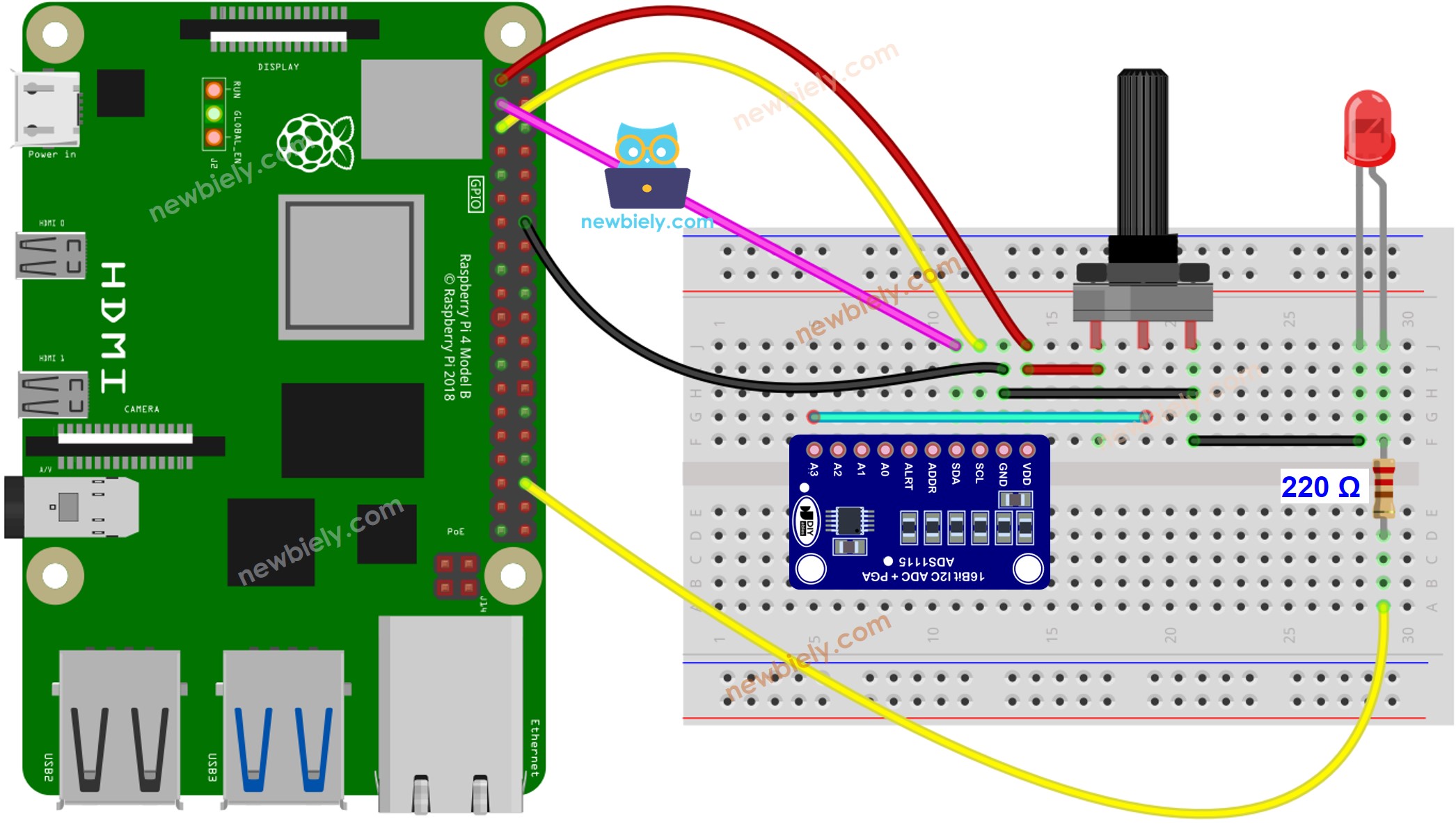
선연결

이 이미지는 Fritzing을 사용하여 만들어졌습니다. 이미지를 확대하려면 클릭하세요.
배선 구성을 간단하고 체계적으로 만들기 위해, Raspberry Pi용 스크루 터미널 블록 실드 사용을 권장합니다. 이 실드는 아래와 같이 더욱 안정적이고 관리하기 쉬운 연결을 제공합니다:

라즈베리 파이 코드
자세한 사용 방법
- Raspberry Pi에 Raspbian 또는 다른 Raspberry Pi 호환 운영 체제가 설치되어 있는지 확인하십시오.
- Raspberry Pi가 PC와 동일한 로컬 네트워크에 연결되어 있는지 확인하십시오.
- 일부 라이브러리를 설치해야 하는 경우 Raspberry Pi가 인터넷에 연결되어 있는지 확인하십시오.
- Raspberry Pi를 처음 사용하는 경우, 라즈베리 파이 - 소프트웨어 설치을 참조하십시오.
- Linux와 macOS에서는 내장 SSH 클라이언트를 사용하거나 Windows에서는 PuTTY를 사용하여 Raspberry Pi에 SSH로 PC를 연결하십시오. PC를 SSH로 Raspberry Pi에 연결하는 방법을 참조하십시오.
- RPi.GPIO 라이브러리가 설치되어 있는지 확인하십시오. 설치되어 있지 않으면 다음 명령어를 사용하여 설치하십시오:
sudo apt-get update
sudo apt-get install python3-rpi.gpio
- Raspberry Pi 터미널에서 다음 명령어를 실행하여 Adafruit_ADS1x15 라이브러리를 설치하세요.
sudo pip install Adafruit-ADS1x15
- 파이썬 스크립트 파일 potentiometer_fade_led.py을(를) 만들고 다음 코드를 추가하십시오.
/*
* 이 라즈베리 파이 코드는 newbiely.kr 에서 개발되었습니다
* 이 라즈베리 파이 코드는 어떠한 제한 없이 공개 사용을 위해 제공됩니다.
* 상세한 지침 및 연결도에 대해서는 다음을 방문하세요:
* https://newbiely.kr/tutorials/raspberry-pi/raspberry-pi-potentiometer-fade-led
*/
import time
import Adafruit_ADS1x15
import RPi.GPIO as GPIO
# Create an ADS1115 ADC object
adc = Adafruit_ADS1x15.ADS1115()
# Set the gain to ±4.096V (adjust if needed)
GAIN = 1
# Define the GPIO pin for the LED
LED_PIN = 16 # Change this to the appropriate GPIO pin
# Set up GPIO for the LED
GPIO.setmode(GPIO.BCM)
GPIO.setup(LED_PIN, GPIO.OUT)
# Define the PWM parameters
PWM_FREQUENCY = 1000 # PWM frequency in Hz
PWM_DUTY_CYCLE = 0 # Initial duty cycle (0 to 100)
# Create a PWM object
pwm_led = GPIO.PWM(LED_PIN, PWM_FREQUENCY)
# Start PWM with the initial duty cycle
pwm_led.start(PWM_DUTY_CYCLE)
# Main loop to read the analog value and control LED brightness
try:
while True:
# Read the raw analog value from channel A3
raw_value = adc.read_adc(3, gain=GAIN)
# Convert the raw value to voltage
voltage = raw_value / 32767.0 * 4.096 # Assumes 4.096 V range for GAIN=1
# Print the results
print("Raw Value: {} \t Voltage: {:.2f} V".format(raw_value, voltage))
# Map the analog value to a duty cycle percentage (0 to 100)
duty_cycle = int((raw_value / 32767.0) * 100)
# Update the LED brightness with PWM
pwm_led.ChangeDutyCycle(duty_cycle)
# Add a delay between readings (adjust as needed)
time.sleep(0.1)
except KeyboardInterrupt:
print("\nExiting the program.")
# Stop PWM and clean up GPIO on exit
pwm_led.stop()
GPIO.cleanup()
- 파일을 저장하고 터미널에서 다음 명령을 실행하여 Python 스크립트를 실행합니다:
python3 potentiometer_fade_led.py
- 가변 저항기를 돌리세요.
- LED의 밝기를 확인하세요.
- 터미널의 출력을 확인하세요.
PuTTY - Raspberry Pi
Raw Value: 19736 Voltage: 2.39 V
Raw Value: 19075 Voltage: 2.31 V
Raw Value: 18409 Voltage: 2.23 V
Raw Value: 17747 Voltage: 2.15 V
Raw Value: 17086 Voltage: 2.07 V
스크립트는 터미널에서 Ctrl + C를 누를 때까지 계속해서 무한 루프로 실행됩니다.
동영상
비디오 제작은 시간이 많이 걸리는 작업입니다. 비디오 튜토리얼이 학습에 도움이 되었다면, YouTube 채널 을 구독하여 알려 주시기 바랍니다. 비디오에 대한 높은 수요가 있다면, 비디오를 만들기 위해 노력하겠습니다.
