공개: 이 포스팅 에 제공된 일부 링크는 아마존 제휴 링크입니다. 이 포스팅은 쿠팡 파트너스 활동의 일환으로, 이에 따른 일정액의 수수료를 제공받습니다.
TCS3200D/TCS230 컬러 센서에 대하여
TCS3200D/TCS230 센서는 광학 필터링을 통한 색상 감지를 위해 8×8 그리드로 배열된 포토다이오드 매트릭스를 활용합니다. 64개 소자 배열에서 16개의 포토다이오드는 적색 스펙트럼 필터를 가지고, 다른 16개는 녹색 필터를, 16개는 청색 필터를 사용하며, 나머지 16개는 필터 없이(투명 응답) 동작합니다. 색상 측정은 특정 필터 세트를 활성화하고 결과적인 주파수 변조 구형파 출력을 분석하여 이루어집니다.
일반적인 모듈의 내장 백색 LED 어레이는 대상에 일정한 조명을 제공하여, 외부 조명 변화에 관계없이 측정 안정성을 유지하고 어두운 환경에서의 성능을 향상시킵니다.
핀아웃
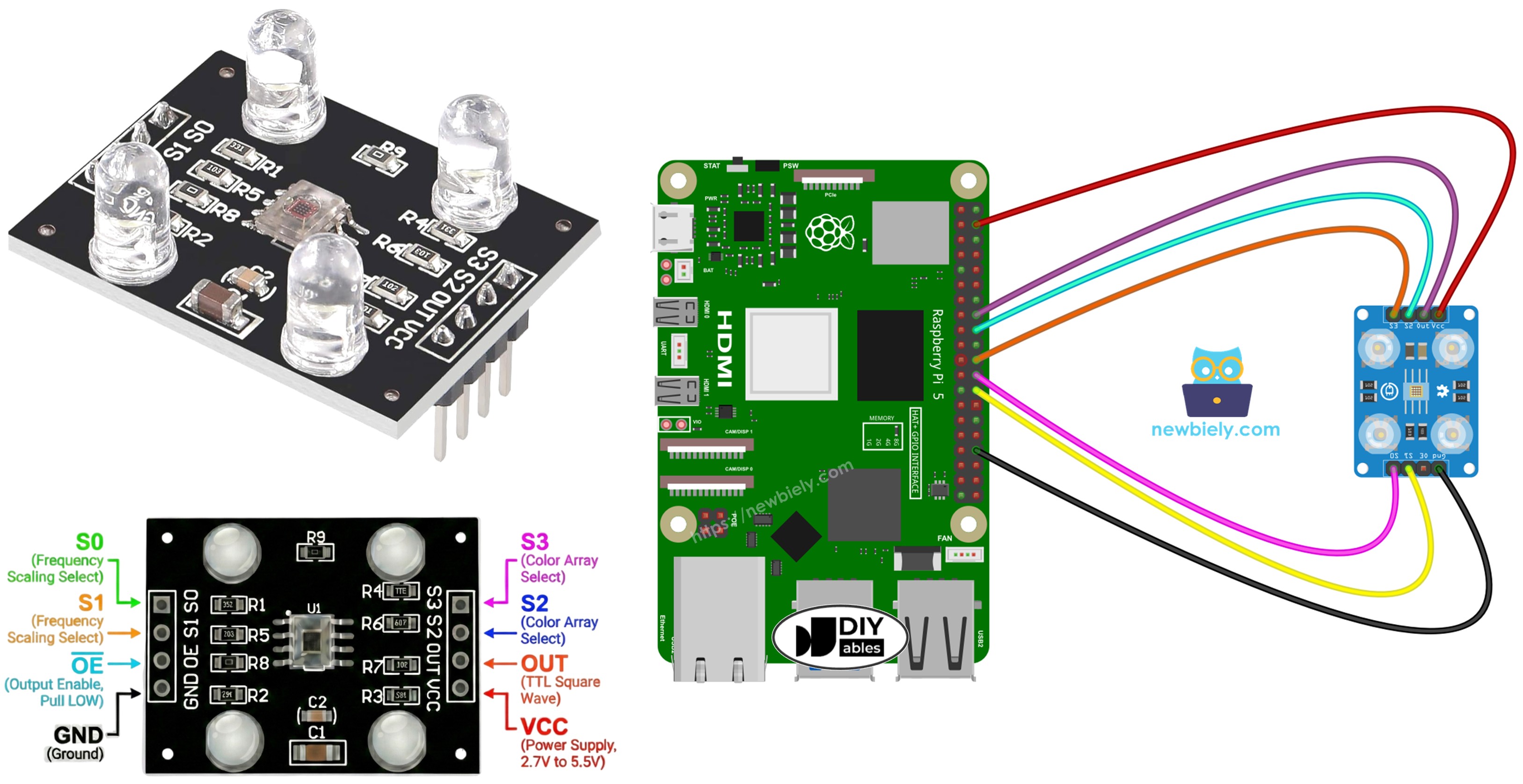
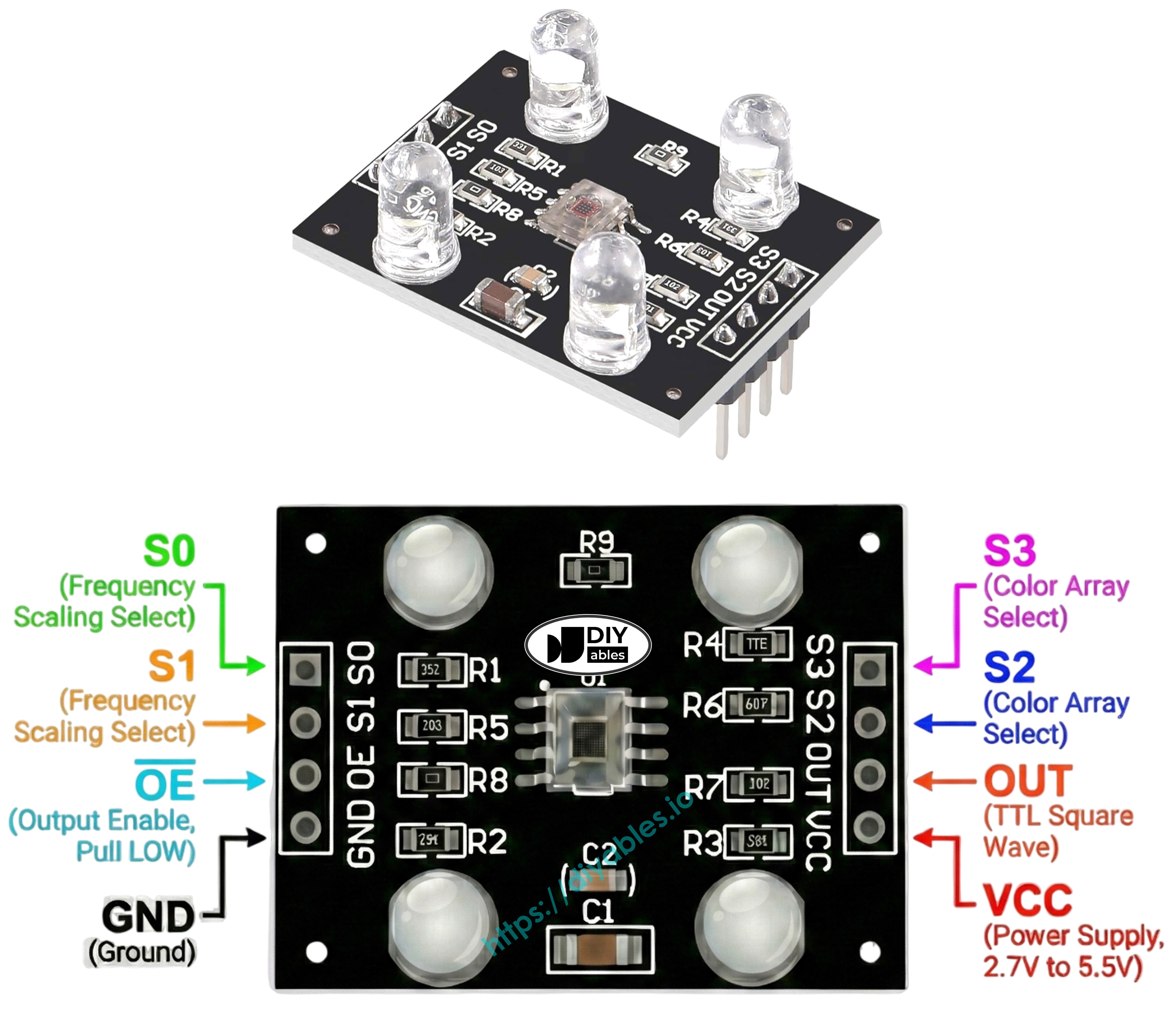
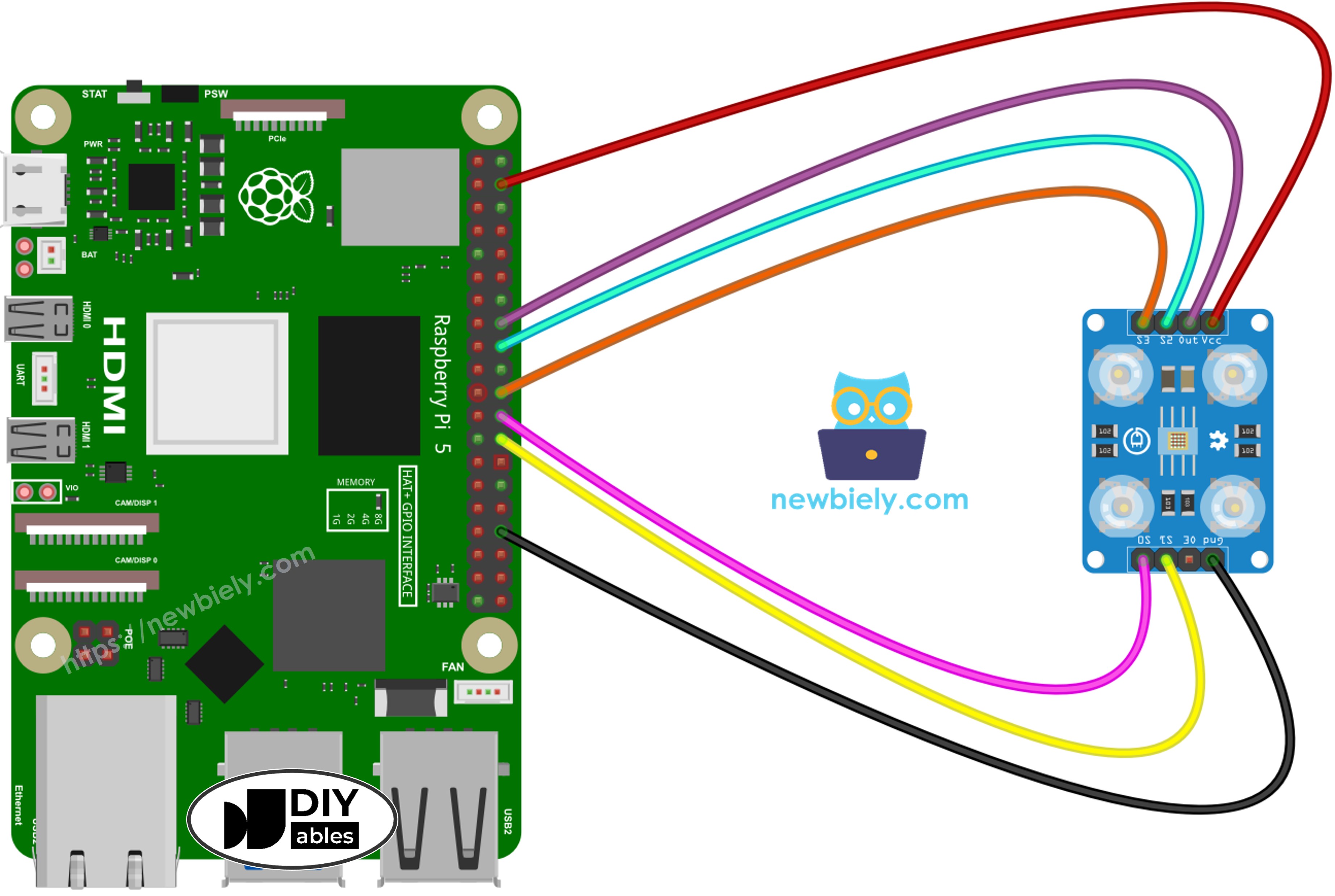
TCS3200D/TCS230 센서 보드의 사용 가능한 연결:
VCC 핀: 공급 전압 입력(+5V).
GND 핀: 접지 기준(0V).
S0, S1 핀: 출력 주파수 스케일링 선택기.
S2, S3 핀: 색상 채널 필터 선택기.
OUT 핀: 주파수 변조 구형파 출력.
OE 핀: 출력 활성화 입력(LOW일 때 활성화). 표준 모듈은 일반적으로 내부적으로 GND에 연결되어 있습니다. 연결되지 않은 경우 수동으로 GND에 연결합니다.
작동 원리
두 가지 중요한 설정이 센서 동작을 제어합니다: 어떤 색상 채널을 활성화할지와 어떤 출력 신호 강도를 생성할지. 두 쌍의 제어 입력이 이 기능을 관리합니다:
주파수 스케일링 제어(S0 및 S1 핀):
S0=LOW, S1=LOW: 전원 끄기 상태
S0=LOW, S1=HIGH: 2% 스케일링 계수
S0=HIGH, S1=LOW: 20% 스케일링 계수
S0=HIGH, S1=HIGH: 100% 스케일링 계수(전체 속도)
색상 채널 선택(S2 및 S3 핀):
S2=LOW, S3=LOW: 적색 포토다이오드 활성
S2=LOW, S3=HIGH: 청색 포토다이오드 활성
S2=HIGH, S3=LOW: 투명 포토다이오드 활성(필터 없음)
S2=HIGH, S3=HIGH: 녹색 포토다이오드 활성
OUT 핀은 약 2Hz에서 500kHz 범위의 구형파 주파수를 출력합니다. 주파수는 빛의 강도에 따라 증가합니다 — 밝은 조명일수록 주파수가 높아집니다. 펄스 지속 시간을 측정함으로써(반비례 관계 — 지속 시간이 짧을수록 빛이 강함), 보정을 통해 표준 0-255 RGB 형식으로 변환할 수 있습니다.
보정은 원시 측정값에서 환경적 간섭을 제거합니다. LED 출력 강도, 대상 거리, 재료 반사율, 실내 조명 등의 변수가 측정값에 영향을 줍니다. 이를 체계적인 오류로 생각하고 측정이 필요합니다. 보정 루틴은 모든 색상 채널에서 최소 및 최대 펄스 폭을 식별하여, 원시 데이터를 배포 환경에 맞는 정확한 0–255 RGB 값으로 변환하기 위한 기준 경계를 설정합니다.
/* * 이 라즈베리 파이 코드는 newbiely.kr 에서 개발되었습니다 * 이 라즈베리 파이 코드는 어떠한 제한 없이 공개 사용을 위해 제공됩니다. * 상세한 지침 및 연결도에 대해서는 다음을 방문하세요: * https://newbiely.kr/tutorials/raspberry-pi/raspberry-pi-tcs3200d-tcs230-color-sensor */import RPi.GPIOasGPIOimport time# Pin Definitions (all on same physical row for easy wiring)OUT_PIN = 23 # Raspberry Pi GPIO23 pin connected to OUT (physical pin 16)S0_PIN = 8 # Raspberry Pi GPIO8 pin connected to S0 (physical pin 24)S1_PIN = 7 # Raspberry Pi GPIO7 pin connected to S1 (physical pin 26)S2_PIN = 24 # Raspberry Pi GPIO24 pin connected to S2 (physical pin 18)S3_PIN = 25 # Raspberry Pi GPIO25 pin connected to S3 (physical pin 22)# Set up GPIO modeGPIO.setmode(GPIO.BCM)GPIO.setup(S0_PIN, GPIO.OUT)GPIO.setup(S1_PIN, GPIO.OUT)GPIO.setup(S2_PIN, GPIO.OUT)GPIO.setup(S3_PIN, GPIO.OUT)GPIO.setup(OUT_PIN, GPIO.IN)# Set frequency scaling to 2% (S0=LOW, S1=HIGH) for reliable timing on Raspberry PiGPIO.output(S0_PIN, GPIO.LOW)GPIO.output(S1_PIN, GPIO.HIGH)# Variables to track min and max pulse widths for each colorred_min = 999999red_max = 0green_min = 999999green_max = 0blue_min = 999999blue_max = 0def read_pulse_width():"""Read the pulse width from OUT pin in microseconds""" # Wait for pulse to go HIGH timeout = time.time() + 0.1 # 100ms timeout while GPIO.input(OUT_PIN) == GPIO.LOW: if time.time() > timeout: return 0 # Measure HIGH pulse duration pulse_start = time.time() timeout = time.time() + 0.1 while GPIO.input(OUT_PIN) == GPIO.HIGH: if time.time() > timeout: return 0 pulse_end = time.time() # Return duration in microseconds return int((pulse_end - pulse_start) * 1000000)def read_red(): """Read red color pulse width"""GPIO.output(S2_PIN, GPIO.LOW)GPIO.output(S3_PIN, GPIO.LOW) time.sleep(0.01)return read_pulse_width()def read_green():"""Read green color pulse width""" GPIO.output(S2_PIN, GPIO.HIGH) GPIO.output(S3_PIN, GPIO.HIGH) time.sleep(0.01) return read_pulse_width()def read_blue(): """Read blue color pulse width"""GPIO.output(S2_PIN, GPIO.LOW)GPIO.output(S3_PIN, GPIO.HIGH) time.sleep(0.01)return read_pulse_width()try:print("=== TCS3200 Calibration ===")print("Point the sensor at different objects (white, black, colors).")print("Min and Max values are tracked automatically.")print("When values look stable, note them down for the next code.")print()whileTrue:# Read all three colors (average of 3 readings for stability) red_readings = [read_red() for _ inrange(3)] green_readings = [read_green() for _ inrange(3)] blue_readings = [read_blue() for _ inrange(3)] red_pw = sum(r for r in red_readings if r > 0) // max(1, len([r for r in red_readings if r > 0])) green_pw = sum(g for g in green_readings if g > 0) // max(1, len([g for g in green_readings if g > 0])) blue_pw = sum(b for b in blue_readings if b > 0) // max(1, len([b for b in blue_readings if b > 0]))# Update min valuesif red_pw > 0 and red_pw < red_min: red_min = red_pwif green_pw > 0 and green_pw < green_min: green_min = green_pwif blue_pw > 0 and blue_pw < blue_min: blue_min = blue_pw# Update max valuesif red_pw > red_max: red_max = red_pwif green_pw > green_max: green_max = green_pwif blue_pw > blue_max: blue_max = blue_pw# Display current readings and min/maxprint("-" * 42)print(f"Red PW = {red_pw} - Green PW = {green_pw} - Blue PW = {blue_pw}")print(f" Min -> R:{red_min} G:{green_min} B:{blue_min}")print(f" Max -> R:{red_max} G:{green_max} B:{blue_max}") time.sleep(0.5)exceptKeyboardInterrupt:print("\nCalibration stopped")print(f"\nFinal calibration values:")print(f"redMin = {red_min}, redMax = {red_max}")print(f"greenMin = {green_min}, greenMax = {green_max}")print(f"blueMin = {blue_min}, blueMax = {blue_max}")finally:GPIO.cleanup()
빠른 시작
코드를 복사하여 파일에 저장합니다. 예: tcs3200_calibration.py
스크립트를 실행합니다:
PuTTY - Raspberry Pi
python3 tcs3200_calibration.py
센서를 다양한 표면에 향하게 합니다: 흰색 재료(프린터 용지), 검정색 물체, 다양한 색상의 물체
Min/Max 경계가 자동으로 업데이트되는 것을 확인합니다.
값이 안정화되면(일반적으로 10-20초), Ctrl+C를 눌러 중지합니다.
표시된 여섯 개의 보정 매개변수를 기록합니다.
PuTTY - Raspberry Pi
=== TCS3200 Calibration ===
Point the sensor at different objects (white, black, colors).
Min and Max values are tracked automatically.
When values look stable, note them down for the next code.
------------------------------------------
Red PW = 42 - Green PW = 55 - Blue PW = 60
Min -> R:42 G:55 B:60
Max -> R:42 G:55 B:60
------------------------------------------
Red PW = 210 - Green PW = 185 - Blue PW = 172
Min -> R:42 G:55 B:60
Max -> R:210 G:185 B:172
------------------------------------------
Red PW = 44 - Green PW = 57 - Blue PW = 61
Min -> R:42 G:55 B:60
Max -> R:210 G:185 B:172
------------------------------------------
Calibration stopped
Final calibration values:
redMin = 42, redMax = 210
greenMin = 55, greenMax = 185
blueMin = 60, blueMax = 172
위 출력에서 추출한 샘플 보정 매개변수:
RedMin = 42, redMax = 210
GreenMin = 55, greenMax = 185
BlueMin = 60, blueMax = 172
Raspberry Pi 코드 - RGB 값 측정
/* * 이 라즈베리 파이 코드는 newbiely.kr 에서 개발되었습니다 * 이 라즈베리 파이 코드는 어떠한 제한 없이 공개 사용을 위해 제공됩니다. * 상세한 지침 및 연결도에 대해서는 다음을 방문하세요: * https://newbiely.kr/tutorials/raspberry-pi/raspberry-pi-tcs3200d-tcs230-color-sensor */import RPi.GPIOasGPIOimport time# Pin Definitions (all on same physical row for easy wiring)OUT_PIN = 23 # Raspberry Pi GPIO23 pin connected to OUT (physical pin 16)S0_PIN = 8 # Raspberry Pi GPIO8 pin connected to S0 (physical pin 24)S1_PIN = 7 # Raspberry Pi GPIO7 pin connected to S1 (physical pin 26)S2_PIN = 24 # Raspberry Pi GPIO24 pin connected to S2 (physical pin 18)S3_PIN = 25 # Raspberry Pi GPIO25 pin connected to S3 (physical pin 22)# Calibration values - REPLACE with your calibrated values!red_min = 0red_max = 0green_min = 0green_max = 0blue_min = 0blue_max = 0# Set up GPIO modeGPIO.setmode(GPIO.BCM)GPIO.setup(S0_PIN, GPIO.OUT)GPIO.setup(S1_PIN, GPIO.OUT)GPIO.setup(S2_PIN, GPIO.OUT)GPIO.setup(S3_PIN, GPIO.OUT)GPIO.setup(OUT_PIN, GPIO.IN)# Set frequency scaling to 2% (S0=LOW, S1=HIGH) for reliable timing on Raspberry PiGPIO.output(S0_PIN, GPIO.LOW)GPIO.output(S1_PIN, GPIO.HIGH)def read_pulse_width():"""Read the pulse width from OUT pin in microseconds""" # Wait for pulse to go HIGH timeout = time.time() + 0.1 # 100ms timeout while GPIO.input(OUT_PIN) == GPIO.LOW: if time.time() > timeout: return 0 # Measure HIGH pulse duration pulse_start = time.time() timeout = time.time() + 0.1 while GPIO.input(OUT_PIN) == GPIO.HIGH: if time.time() > timeout: return 0 pulse_end = time.time() # Return duration in microseconds return int((pulse_end - pulse_start) * 1000000)def read_red(): """Read red color pulse width"""GPIO.output(S2_PIN, GPIO.LOW)GPIO.output(S3_PIN, GPIO.LOW) time.sleep(0.01)return read_pulse_width()def read_green():"""Read green color pulse width""" GPIO.output(S2_PIN, GPIO.HIGH) GPIO.output(S3_PIN, GPIO.HIGH) time.sleep(0.01) return read_pulse_width()def read_blue(): """Read blue color pulse width"""GPIO.output(S2_PIN, GPIO.LOW)GPIO.output(S3_PIN, GPIO.HIGH) time.sleep(0.01)return read_pulse_width()def map_value(value, in_min, in_max, out_min, out_max):"""Map value from one range to another""" if in_max == in_min: return out_min return int((value - in_min) * (out_max - out_min) / (in_max - in_min) + out_min)def constrain(value, min_val, max_val): """Constrain value between min and max"""returnmax(min_val, min(value, max_val))try:print("TCS3200 Color Sensor - RGB Reading")print()whileTrue:# Read pulse widths for all colors (average of 3 readings for stability) red_readings = [read_red() for _ inrange(3)] green_readings = [read_green() for _ inrange(3)] blue_readings = [read_blue() for _ inrange(3)] red_pw = sum(r for r in red_readings if r > 0) // max(1, len([r for r in red_readings if r > 0])) green_pw = sum(g for g in green_readings if g > 0) // max(1, len([g for g in green_readings if g > 0])) blue_pw = sum(b for b in blue_readings if b > 0) // max(1, len([b for b in blue_readings if b > 0]))# Convert to 0-255 RGB values# Lower pulse width = brighter = higher RGB value red_value = map_value(red_pw, red_min, red_max, 255, 0) green_value = map_value(green_pw, green_min, green_max, 255, 0) blue_value = map_value(blue_pw, blue_min, blue_max, 255, 0)# Constrain to 0-255 range red_value = constrain(red_value, 0, 255) green_value = constrain(green_value, 0, 255) blue_value = constrain(blue_value, 0, 255)# Display RGB valuesprint(f"Red = {red_value} - Green = {green_value} - Blue = {blue_value}") time.sleep(0.5)exceptKeyboardInterrupt:print("\nProgram stopped")finally:GPIO.cleanup()