아두이노 우노 R4 LED 지연 없이 깜빡임
Arduino UNO R4가 두 가지 작업을 수행해야 한다고 상상해 보세요: LED를 깜빡이고 버튼이 눌렸을 때 감지하는 것입니다. delay() 함수를 사용하면 Arduino UNO R4가 일부 버튼 누름을 놓칠 수 있습니다. 이 튜토리얼에서는 버튼을 모니터링하여 모든 버튼 누름을 감지하면서 Arduino UNO R4가 LED를 깜빡이게 하는 방법을 배웁니다.
아래의 세 가지 예를 살펴보고 그 차이점을 비교해 보겠습니다.
- Arduino UNO R4은 delay() 함수를 사용하여 LED를 깜박이게 합니다.
- Arduino UNO R4은 millis() 함수를 사용하여 LED를 깜박이게 합니다.
- Arduino UNO R4은 ezLED 라이브러리를 사용하여 LED를 깜박이게 합니다.

※ 주의:
- 이 방법은 단순히 LED를 깜빡이게 하고 버튼 상태를 확인하는 것 이상의 역할을 합니다. 이것은 Arduino UNO R4가 여러 작업을 중단 없이 동시에 수행할 수 있도록 합니다.
- 이 튜토리얼은 작동 방식을 배우는 데 도움이 되는 자세한 정보를 제공합니다. 간단하게 하기 위해 Arduino UNO R4 - LED 라이브러리를 사용할 수 있습니다.
준비물
| 1 | × | Arduino UNO R4 WiFi or Arduino UNO R4 Minima | ||
| 1 | × | (또는) DIYables STEM V4 IoT, Compatible with Arduino Uno R4 WiFi | 쿠팡 | 아마존 | |
| 1 | × | USB 케이블 타입-A to 타입-C (USB-A PC용) | 쿠팡 | 아마존 | |
| 1 | × | USB 케이블 타입-C to 타입-C (USB-C PC용) | 아마존 | |
| 1 | × | LED | 쿠팡 | 아마존 | |
| 1 | × | LED Module | 아마존 | |
| 1 | × | 220Ω Resistor | 아마존 | |
| 1 | × | 캡이 있는 버튼 | 쿠팡 | 아마존 | |
| 1 | × | 버튼 키트 | 쿠팡 | 아마존 | |
| 1 | × | 패널 장착 푸시 버튼 | 아마존 | |
| 1 | × | 푸시 버튼 모듈 | 아마존 | |
| 1 | × | 브레드보드 | 쿠팡 | 아마존 | |
| 1 | × | 점퍼케이블 | 쿠팡 | 아마존 | |
| 1 | × | (추천) 아두이노 우노 R4용 스크루 터미널 블록 쉴드 | 쿠팡 | 아마존 | |
| 1 | × | (추천) 아두이노 우노 R4용 브레드보드 쉴드 | 쿠팡 | 아마존 | |
| 1 | × | (추천) 아두이노 우노 R4용 케이스 | 쿠팡 | 아마존 | |
| 1 | × | (추천) 아두이노 우노 R4용 전원 분배기 | 쿠팡 | 아마존 | |
| 1 | × | (추천) 아두이노 우노용 프로토타이핑 베이스 플레이트 & 브레드보드 키트 | 아마존 |
공개: 이 포스팅 에 제공된 일부 링크는 아마존 제휴 링크입니다. 이 포스팅은 쿠팡 파트너스 활동의 일환으로, 이에 따른 일정액의 수수료를 제공받습니다.
LED 및 버튼에 대하여
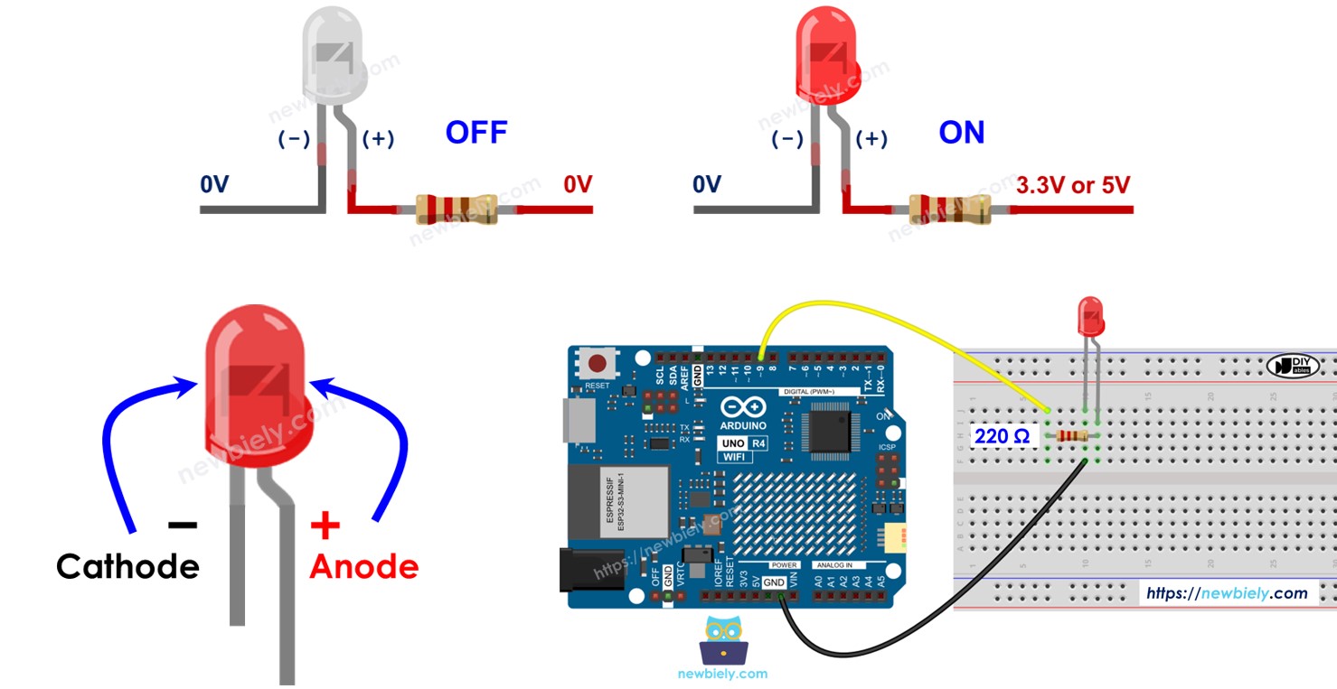
이 튜토리얼에서 LED와 버튼(핀아웃, 작동 방식, 프로그래밍 방법 등)에 대해 알아보세요.
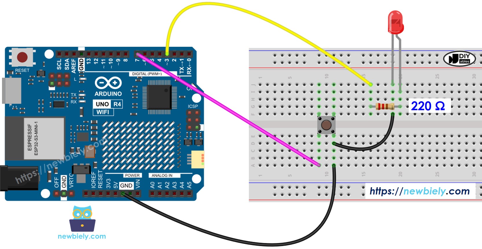
선연결

이 이미지는 Fritzing을 사용하여 만들어졌습니다. 이미지를 확대하려면 클릭하세요.
Arduino Uno R4와 기타 부품에 전원을 공급하는 가장 효과적인 방법을 확인하시려면, 아래 링크를 참조하세요: 아두이노 우노 R4 전원 공급 방법.
아두이노 UNO R4 코드 - 지연 포함
/*
* 이 아두이노 우노 R4 코드는 newbiely.kr 에서 개발되었습니다
* 이 아두이노 우노 R4 코드는 어떠한 제한 없이 공개 사용을 위해 제공됩니다.
* 상세한 지침 및 연결도에 대해서는 다음을 방문하세요:
* https://newbiely.kr/tutorials/arduino-uno-r4/arduino-uno-r4-blink-led-without-delay
*/
#define LED_PIN 3 // The Arduino UNO R4 pin connected to the LED
#define BUTTON_PIN 7 // The Arduino UNO R4 pin connected to the button
#define BLINK_INTERVAL 1000 // interval at which to blink LED (milliseconds)
int led_state = LOW; // led_state used to set the LED
int prev_button_state = LOW; // will store last time button was updated
void setup() {
Serial.begin(9600);
// set the digital pin as output
pinMode(LED_PIN, OUTPUT);
// set the digital pin as an input
pinMode(BUTTON_PIN, INPUT_PULLUP);
}
void loop() {
// if the LED is off turn it on and vice-versa
led_state = (led_state == LOW) ? HIGH : LOW;
// set the LED with the led_state of the variable
digitalWrite(LED_PIN, led_state);
delay(BLINK_INTERVAL); // If button is pressed during this time, Arduino CANNOT detect
int button_state = digitalRead(BUTTON_PIN);
if (button_state != prev_button_state) {
// print out the state of the button:
Serial.println(button_state);
// save the last state of button
prev_button_state = button_state;
}
// DO OTHER WORKS HERE
}
자세한 사용 방법
다음 지침을 단계별로 따르세요:
- Arduino Uno R4 WiFi/Minima를 처음 사용하는 경우 아두이노 우노 R4 - 소프트웨어 설치을 참조하십시오.
- 제공된 다이어그램에 따라 구성 요소를 연결하십시오.
- USB 케이블을 사용하여 Arduino Uno R4 보드를 컴퓨터에 연결하십시오.
- 컴퓨터에서 Arduino IDE를 실행하십시오.
- 적절한 Arduino Uno R4 보드(예: Arduino Uno R4 WiFi)와 COM 포트를 선택하십시오.
- 제공된 코드를 복사하여 Arduino IDE에 붙여넣으십시오.
- Arduino IDE에서 Upload 버튼을 클릭하여 코드를 Arduino UNO R4로 전송하십시오.

- 시리얼 모니터를 엽니다.
- 버튼을 네 번 누릅니다.
- LED를 관찰합니다: 매초 켜지고 꺼집니다.
- 시리얼 모니터의 디스플레이를 확인합니다.
COM6
1
0
Autoscroll
Clear output
9600 baud
Newline
- 일부 버튼 눌림은 Arduino UNO R4가 지연 중에 아무 작업도 수행할 수 없기 때문에 시리얼 모니터에 표시되지 않았습니다. 그 결과, 해당 눌림을 감지하지 못합니다.
아두이노 UNO R4 코드 - 지연 없이
/*
* 이 아두이노 우노 R4 코드는 newbiely.kr 에서 개발되었습니다
* 이 아두이노 우노 R4 코드는 어떠한 제한 없이 공개 사용을 위해 제공됩니다.
* 상세한 지침 및 연결도에 대해서는 다음을 방문하세요:
* https://newbiely.kr/tutorials/arduino-uno-r4/arduino-uno-r4-blink-led-without-delay
*/
#define LED_PIN 3 // The Arduino UNO R4 pin connected to the LED
#define BUTTON_PIN 7 // The Arduino UNO R4 pin connected to the button
#define BLINK_INTERVAL 1000 // interval at which to blink LED (milliseconds)
int led_state = LOW; // led_state used to set the LED
int prev_button_state = LOW; // will store last time button was updated
unsigned long prev_millis = 0; // will store last time LED 1 was updated
void setup() {
Serial.begin(9600);
// set the digital pin as output:
pinMode(LED_PIN, OUTPUT);
// set the digital pin as an input:
pinMode(BUTTON_PIN, INPUT_PULLUP);
}
void loop() {
unsigned long current_millis = millis();
// check to see if it's time to blink the LED 1
if (current_millis - prev_millis >= BLINK_INTERVAL) {
// if the LED is off turn it on and vice-versa:
led_state = (led_state == LOW) ? HIGH : LOW;
// set the LED with the led_state of the variable:
digitalWrite(LED_PIN, led_state);
// save the last time you blinked the LED
prev_millis = current_millis;
}
// check button state's change
int button_state = digitalRead(BUTTON_PIN);
if (button_state != prev_button_state) {
// print out the state of the button:
Serial.println(button_state);
// save the last state of button
prev_button_state = button_state;
}
// DO OTHER WORKS HERE
}
자세한 사용 방법
다음 지침을 단계별로 따르세요:
- 제공된 코드를 Arduino Uno R4에 업로드하십시오.
- 버튼을 네 번 누르세요.
- LED에 주목하세요: 1초마다 켜짐과 꺼짐을 전환합니다.
- 시리얼 모니터에서 출력을 확인하세요.
COM6
1
0
1
0
1
0
1
0
Autoscroll
Clear output
9600 baud
Newline
- 모든 버튼 누르기가 감지되었습니다.
코드 설명
설명은 위의 아두이노 코드의 주석 부분에 있습니다.
작업 추가
이 코드는 두 개의 LED가 서로 다른 시간에 깜빡이게 하고 버튼이 눌렸는지도 확인합니다.
/*
* 이 아두이노 우노 R4 코드는 newbiely.kr 에서 개발되었습니다
* 이 아두이노 우노 R4 코드는 어떠한 제한 없이 공개 사용을 위해 제공됩니다.
* 상세한 지침 및 연결도에 대해서는 다음을 방문하세요:
* https://newbiely.kr/tutorials/arduino-uno-r4/arduino-uno-r4-blink-led-without-delay
*/
#define LED_PIN_1 3 // The Arduino UNO R4 pin connected to the LED 1
#define LED_PIN_2 4 // The Arduino UNO R4 pin connected to the LED 2
#define BUTTON_PIN 7 // The Arduino UNO R4 pin connected to the button
#define BLINK_INTERVAL_1 1000 // interval at which to blink LED 1 (milliseconds)
#define BLINK_INTERVAL_2 500 // interval at which to blink LED 2 (milliseconds)
int led_state_1 = LOW; // led_state used to set the LED 1
int led_state_2 = LOW; // led_state used to set the LED 2
int prev_button_state = LOW; // will store last time button was updated
unsigned long prev_millis_1 = 0; // will store last time LED 1 was updated
unsigned long prev_millis_2 = 0; // will store last time LED 2 was updated
void setup() {
Serial.begin(9600);
// set the digital pin as output:
pinMode(LED_PIN_1, OUTPUT);
pinMode(LED_PIN_2, OUTPUT);
// set the digital pin as an input:
pinMode(BUTTON_PIN, INPUT_PULLUP);
}
void loop() {
unsigned long current_millis = millis();
// check to see if it's time to blink the LED 1
if (current_millis - prev_millis_1 >= BLINK_INTERVAL_1) {
// if the LED is off turn it on and vice-versa:
led_state_1 = (led_state_1 == LOW) ? HIGH : LOW;
// set the LED with the led_state of the variable:
digitalWrite(LED_PIN_1, led_state_1);
// save the last time you blinked the LED
prev_millis_1 = current_millis;
}
// check to see if it's time to blink the LED 2
if (current_millis - prev_millis_2 >= BLINK_INTERVAL_2) {
// if the LED is off turn it on and vice-versa:
led_state_2 = (led_state_2 == LOW) ? HIGH : LOW;
// set the LED with the led_state of the variable:
digitalWrite(LED_PIN_2, led_state_2);
// save the last time you blinked the LED
prev_millis_2 = current_millis;
}
// check button state's change
int button_state = digitalRead(BUTTON_PIN);
if (button_state != prev_button_state) {
// print out the state of the button:
Serial.println(button_state);
// save the last state of button
prev_button_state = button_state;
}
// DO OTHER WORKS HERE
}
동영상
비디오 제작은 시간이 많이 걸리는 작업입니다. 비디오 튜토리얼이 학습에 도움이 되었다면, YouTube 채널 을 구독하여 알려 주시기 바랍니다. 비디오에 대한 높은 수요가 있다면, 비디오를 만들기 위해 노력하겠습니다.
