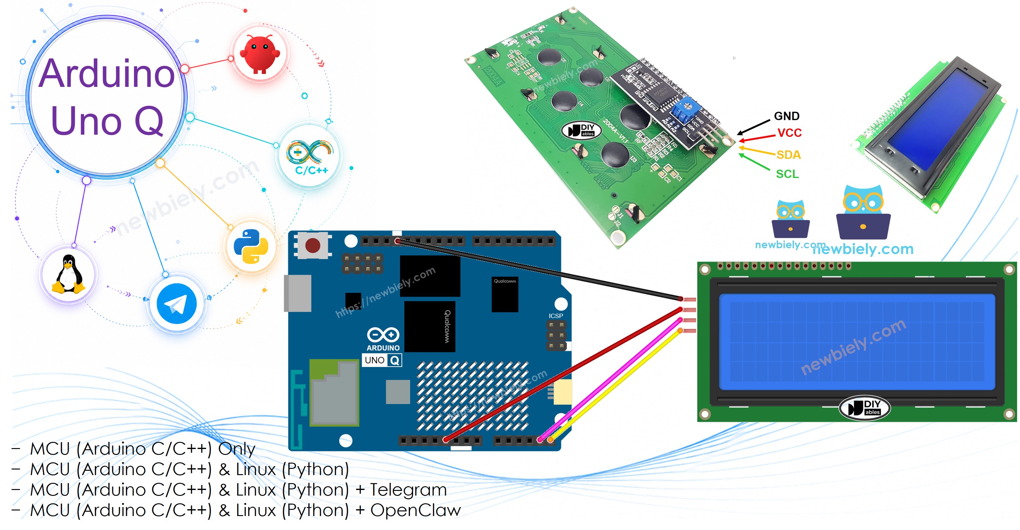
Arduino UNO Q는 두 개의 프로세서를 가지고 있습니다: STM32 MCU (실시간 하드웨어 제어 처리) 및 Qualcomm MPU (Debian Linux 실행). 이 섹션에서는 STM32 MCU만 프로그래밍됩니다. Linux 측은 유휴 상태로 유지됩니다. 이후 섹션에서 두 프로세서가 함께 작동하는 방법을 보여줄 것입니다.
아래 스케치는 LCD의 4개 행 모두에 텍스트를 표시합니다.
/* * 이 Arduino UNO Q 코드는 newbiely.kr 에서 개발되었습니다 * 이 Arduino UNO Q 코드는 어떠한 제한 없이 공개 사용을 위해 제공됩니다. * 상세한 지침 및 연결도에 대해서는 다음을 방문하세요: * https://newbiely.kr/tutorials/arduino-uno-q/arduino-uno-q-lcd-20x4 */#include <DIYables_LCD_I2C.h>DIYables_LCD_I2C lcd(0x27, 20, 4); // I2C address 0x27, 20 columns, 4 rowsvoidsetup() { Monitor.begin(9600); lcd.init(); // Initialize the LCD lcd.backlight(); // Turn on the backlight lcd.setCursor(0, 0); lcd.print("Hello, World!"); lcd.setCursor(0, 1); lcd.print("Arduino UNO Q"); lcd.setCursor(0, 2); lcd.print("LCD 20x4 I2C"); lcd.setCursor(0, 3); lcd.print("DIYables.io"); Monitor.println("LCD 20x4 Hello World done");}voidloop() {}
빠른 단계
Arduino UNO Q를 처음 사용하나요? 진행하기 전에 아두이노 우노 Q 시작하기 튜토리얼을 따라 개발 환경을 준비하십시오.
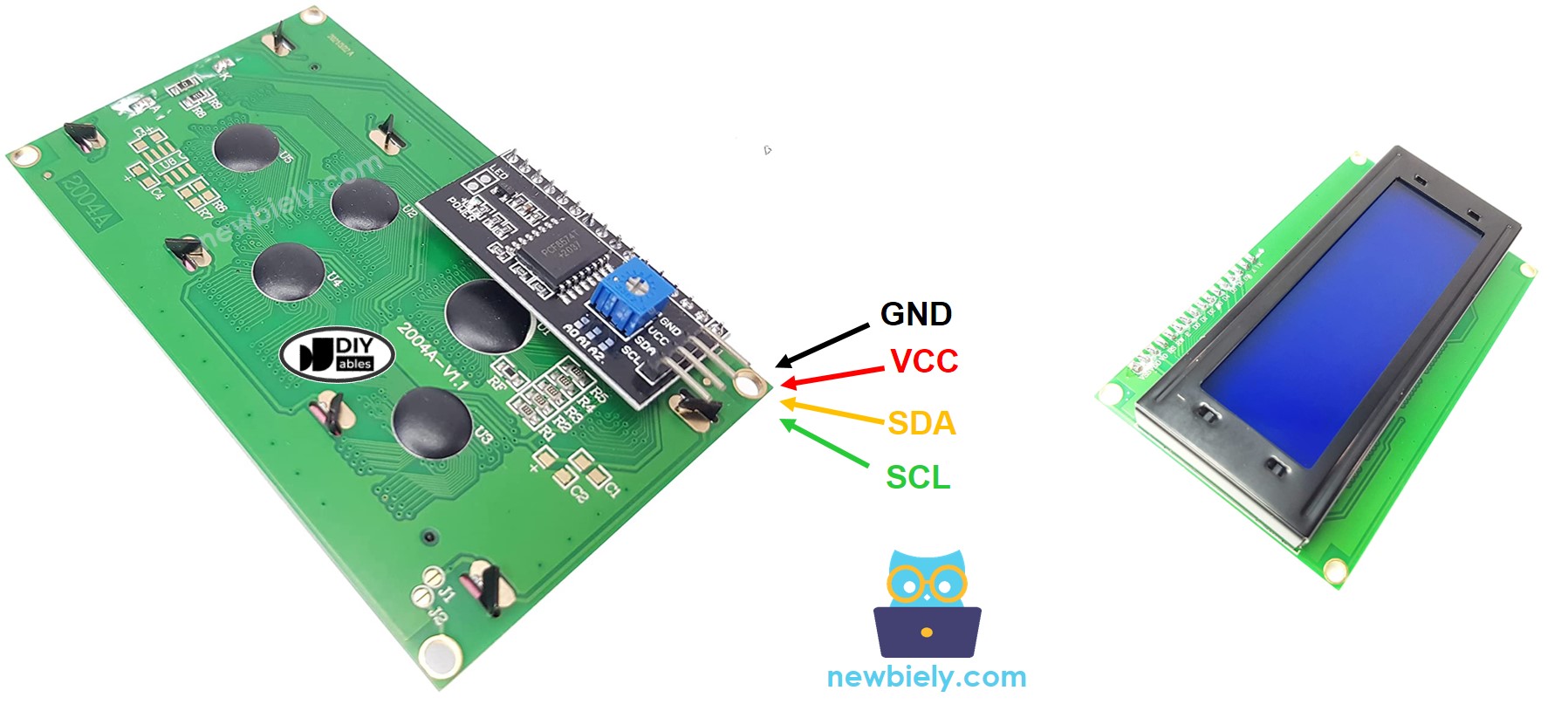
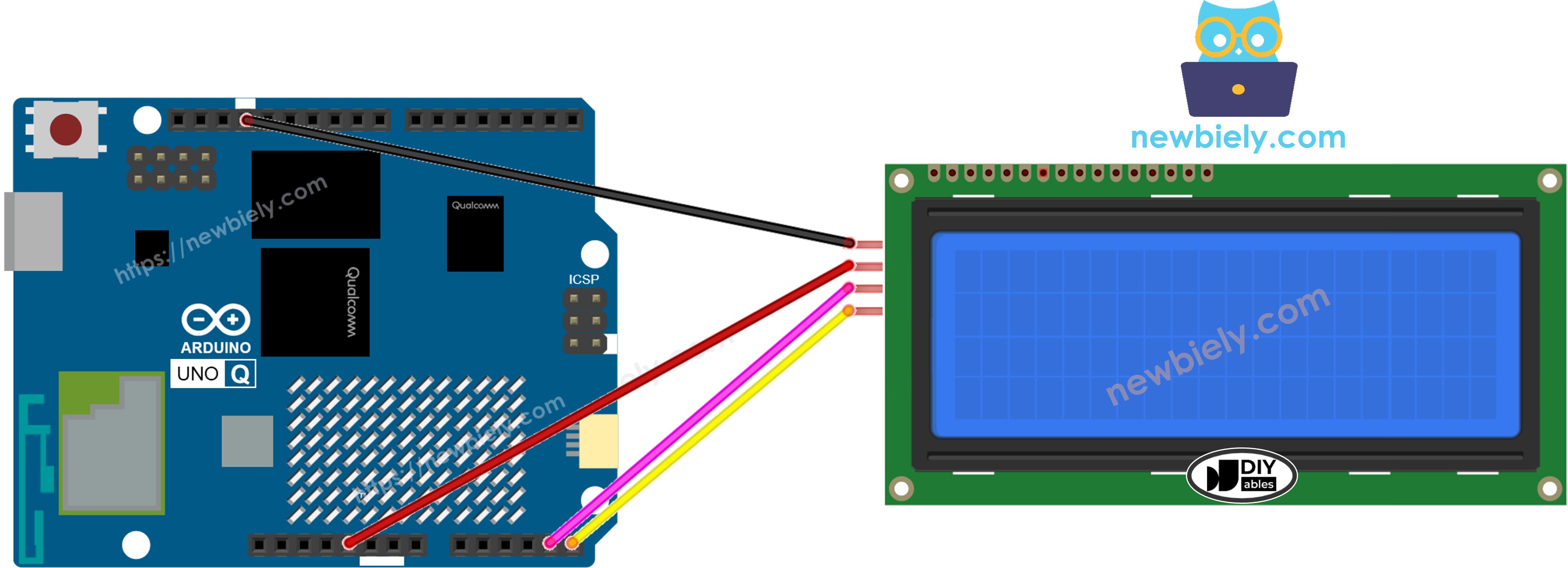
LCD 배선:VCC→5V, GND→GND, SDA→SDA, SCL→SCL을 연결합니다.
연결: USB-C 케이블로 Arduino UNO Q를 컴퓨터에 연결합니다.
Arduino App Lab 열기: Arduino App Lab을 시작하고 Arduino UNO Q를 감지할 때까지 기다립니다.
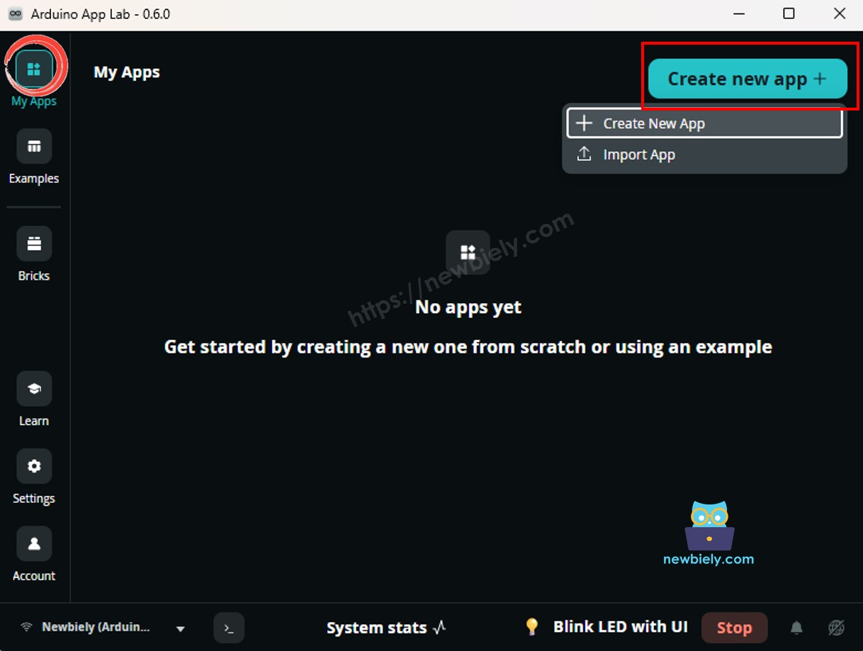
새 앱 생성:Create New App 버튼을 클릭합니다.
앱에 이름을 지정합니다. 예: DIYables_LCD_20x4
Create를 클릭하여 확인합니다.
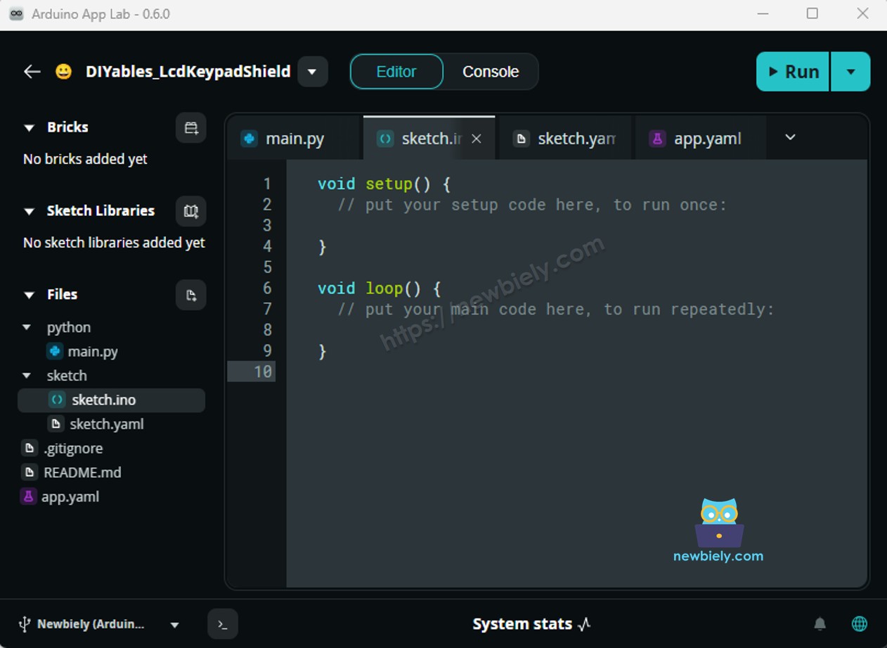
새 앱 내에 폴더 및 파일 집합이 생성된 것을 볼 수 있습니다.
sketch/sketch.ino 파일을 찾습니다. 이것이 MCU 스케치를 붙여넣을 위치입니다.
스케치 붙여넣기: 위의 MCU 코드를 복사하여 스케치 파일에 붙여넣습니다.
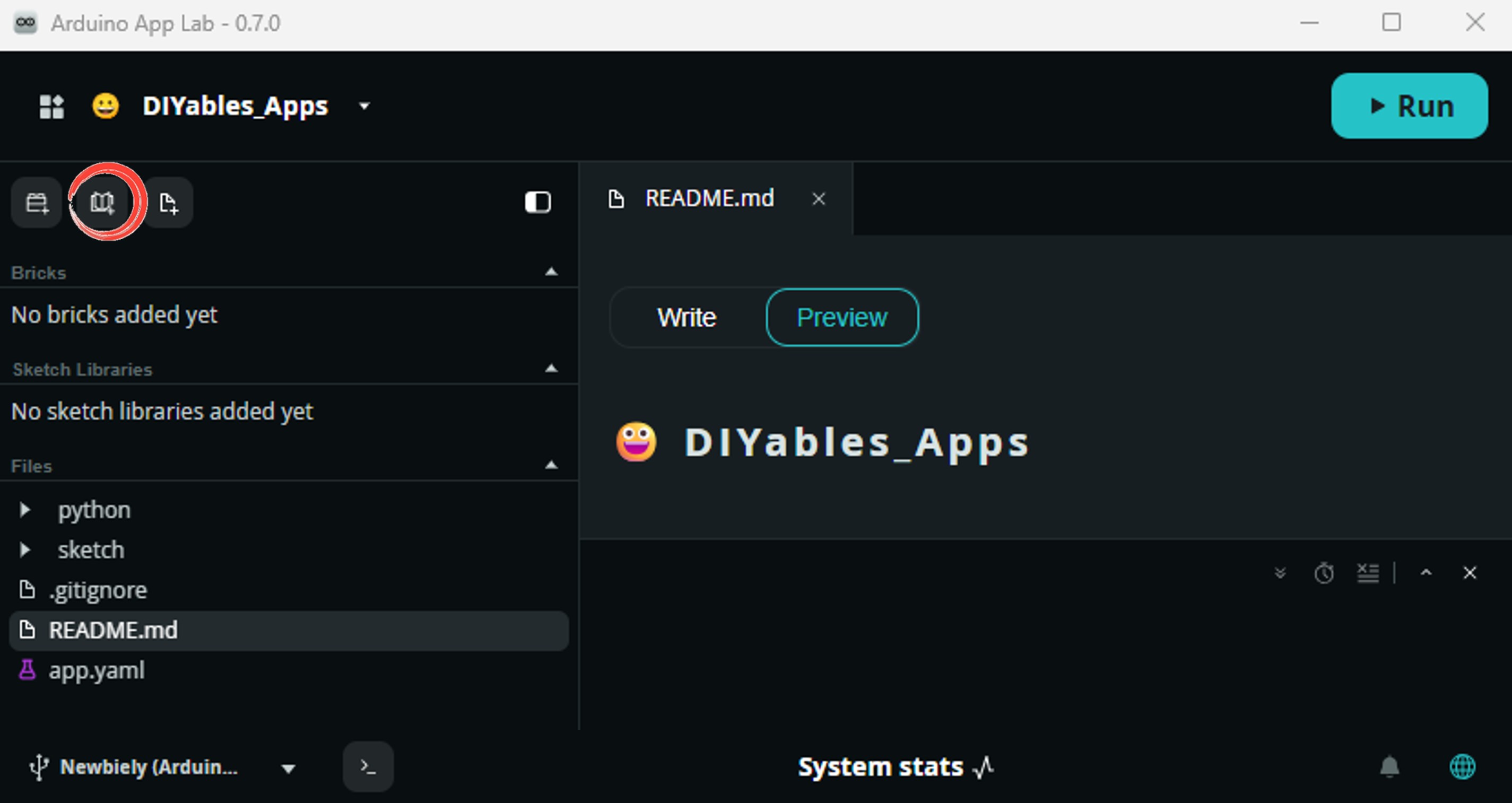
Install the library: Click the Add sketch library button (the open book icon with a + sign) in the left sidebar.
Search for Arduino_RouterBridge created by Arduino and click the Install button.
My Apps/DIYables Apps
Run
Bricks
No bricks added...
Sketch Libraries
No sketch libra...
Files
python
sketch
.gitignore
README.md
app.yaml
sketch.ino
Add sketch library
Arduino_RouterBridge
Arduino_RouterBridgeArduino
This library provides a simple RPC bridge for Arduino UNO Q boards, allowing communication between the board and other devices using MsgPack serialization.
0.4.1
Install
More Info
Search for DIYables LCD I2C created by DIYables.io and click the Install button.
My Apps/DIYables Apps
Run
Bricks
No bricks added...
Sketch Libraries
No sketch libra...
Files
python
sketch
.gitignore
README.md
app.yaml
sketch.ino
Add sketch library
DIYables LCD I2C
DIYables LCD I2CDIYables.io
This library is designed for HD44780-based I2C LCD displays. It provides LiquidCrystal-compatible API plus helper functions (text alignment, progress bars, predefined custom characters). Supports multiple I2C buses (Wire, Wire1, Wire2) for advanced boards like Arduino Giga, Due, and ESP32. Compatible with all Arduino-based platforms including Arduino Uno, Mega, Nano, ESP32, ESP8266, STM32, and Raspberry Pi Pico.
1.0.0
Install
More Info
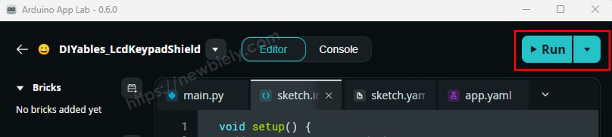
업로드: Arduino App Lab의 Run 버튼을 클릭하여 STM32에 컴파일 및 업로드합니다.
LCD를 보면 모든 4개 행에 텍스트가 표시됩니다: "Hello, World!", "Arduino UNO Q", "LCD 20x4 I2C", "DIYables.io"!
※ 주의:
LCD에 아무것도 표시되지 않거나 검은색 정사각형만 표시되면 I2C 백팩의 대비 포텐셔미터를 조정합니다. 자세한 내용은 LCD I2C 문제 해결을 참조하십시오.
Arduino UNO Q 코드 — LCD 20x4에 텍스트 및 숫자 표시
이 예제는 일반 텍스트 문자열, 정수, 부동소수점, 16진수 숫자를 표시하는 방법을 보여줍니다. 각각은 한 행에 표시됩니다.
/* * 이 Arduino UNO Q 코드는 newbiely.kr 에서 개발되었습니다 * 이 Arduino UNO Q 코드는 어떠한 제한 없이 공개 사용을 위해 제공됩니다. * 상세한 지침 및 연결도에 대해서는 다음을 방문하세요: * https://newbiely.kr/tutorials/arduino-uno-q/arduino-uno-q-lcd-20x4 */#include <DIYables_LCD_I2C.h>DIYables_LCD_I2C lcd(0x27, 20, 4); // I2C address 0x27, 20 columns, 4 rowsvoidsetup() { Monitor.begin(9600); lcd.init(); lcd.backlight();// Row 0: plain text string lcd.setCursor(0, 0); lcd.print("Text: Arduino UNO Q");// Row 1: integerint count = 2025; lcd.setCursor(0, 1); lcd.print("Int: "); lcd.print(count);// Row 2: float (2 decimal places)float voltage = 3.14; lcd.setCursor(0, 2); lcd.print("Float:"); lcd.print(voltage, 2);// Row 3: hexadecimalint value = 255; lcd.setCursor(0, 3); lcd.print("Hex: 0x"); lcd.print(value, HEX); Monitor.println("LCD 20x4 text demo done");}voidloop() {}
scrollDisplayLeft()와 scrollDisplayRight()는 전체 디스플레이 내용을 각 호출당 한 열씩 이동합니다. 모든 4개 행이 함께 이동합니다. 루프에서 짧은 지연과 함께 부드러운 스크롤 효과를 만듭니다.
/* * 이 Arduino UNO Q 코드는 newbiely.kr 에서 개발되었습니다 * 이 Arduino UNO Q 코드는 어떠한 제한 없이 공개 사용을 위해 제공됩니다. * 상세한 지침 및 연결도에 대해서는 다음을 방문하세요: * https://newbiely.kr/tutorials/arduino-uno-q/arduino-uno-q-lcd-20x4 */#include <DIYables_LCD_I2C.h>DIYables_LCD_I2C lcd(0x27, 20, 4); // I2C address 0x27, 20 columns, 4 rowsvoidsetup() { Monitor.begin(9600); lcd.init(); lcd.backlight();// Write text on all 4 rows lcd.setCursor(0, 0); lcd.print("Scroll Left >>>>>"); lcd.setCursor(0, 1); lcd.print("Row 1 scrolling..."); lcd.setCursor(0, 2); lcd.print("Row 2 scrolling..."); lcd.setCursor(0, 3); lcd.print("<<< Scroll Right");delay(1000);// Scroll entire display left 20 steps Monitor.println("Scrolling left...");for (int i = 0; i < 20; i++) { lcd.scrollDisplayLeft();delay(300); }delay(500);// Scroll entire display right 20 steps (back to original) Monitor.println("Scrolling right...");for (int i = 0; i < 20; i++) { lcd.scrollDisplayRight();delay(300); } Monitor.println("LCD 20x4 scroll demo done");}voidloop() {}
빠른 단계
위의 코드를 복사하여 sketch/sketch.ino에 붙여넣습니다.
Arduino App Lab의 Run 버튼을 클릭합니다.
LCD 내용이 왼쪽으로 20칸 이동한 후 원래 위치로 오른쪽으로 20칸 이동합니다.
Arduino UNO Q 코드 — LCD 20x4의 백라이트 제어
lcd.backlight()을 사용하여 I2C 백팩의 백라이트 LED를 켜고 lcd.noBacklight()을 사용하여 끕니다. 이 데모는 켜기 → 끄기 → 켜기 → 깜박임 패턴을 순환합니다.
/* * 이 Arduino UNO Q 코드는 newbiely.kr 에서 개발되었습니다 * 이 Arduino UNO Q 코드는 어떠한 제한 없이 공개 사용을 위해 제공됩니다. * 상세한 지침 및 연결도에 대해서는 다음을 방문하세요: * https://newbiely.kr/tutorials/arduino-uno-q/arduino-uno-q-lcd-20x4 */#include <DIYables_LCD_I2C.h>DIYables_LCD_I2C lcd(0x27, 20, 4); // I2C address 0x27, 20 columns, 4 rowsvoidsetup() { Monitor.begin(9600); lcd.init(); lcd.backlight(); lcd.setCursor(0, 0); lcd.print("Backlight ON"); lcd.setCursor(0, 1); lcd.print("Arduino UNO Q"); lcd.setCursor(0, 2); lcd.print("LCD 20x4 I2C"); lcd.setCursor(0, 3); lcd.print("DIYables.io"); Monitor.println("Backlight ON");delay(2000);// Turn off backlight lcd.noBacklight(); Monitor.println("Backlight OFF");delay(2000);// Turn backlight back on lcd.backlight(); Monitor.println("Backlight ON again");delay(2000);// Blink the backlight 5 times Monitor.println("Blinking backlight...");for (int i = 0; i < 5; i++) { lcd.noBacklight();delay(500); lcd.backlight();delay(500); } Monitor.println("LCD 20x4 backlight demo done");}voidloop() {}
빠른 단계
위의 코드를 복사하여 sketch/sketch.ino에 붙여넣습니다.
Arduino App Lab의 Run 버튼을 클릭합니다.
LCD 백라이트가 켜지고, 끄고, 다시 켜지고, 마지막으로 5번 깜박이는 것을 지켜보세요.
Arduino UNO Q 코드 — LCD 20x4의 커서 및 깜박임
LCD는 두 가지 커서 스타일을 지원합니다: 밑줄 커서 (lcd.cursor()) 및 깜박이는 블록 커서 (lcd.blink()). 이들은 개별적으로 또는 함께 표시될 수 있습니다.
/* * 이 Arduino UNO Q 코드는 newbiely.kr 에서 개발되었습니다 * 이 Arduino UNO Q 코드는 어떠한 제한 없이 공개 사용을 위해 제공됩니다. * 상세한 지침 및 연결도에 대해서는 다음을 방문하세요: * https://newbiely.kr/tutorials/arduino-uno-q/arduino-uno-q-lcd-20x4 */#include <DIYables_LCD_I2C.h>DIYables_LCD_I2C lcd(0x27, 20, 4); // I2C address 0x27, 20 columns, 4 rowsvoidsetup() { Monitor.begin(9600); lcd.init(); lcd.backlight();// Show underscore cursor lcd.setCursor(0, 0); lcd.print("Cursor visible:"); lcd.setCursor(0, 1); lcd.print("Pos (0,1) > "); lcd.cursor(); // Show underscore cursor Monitor.println("cursor() — underscore cursor ON");delay(3000);// Hide cursor lcd.noCursor(); Monitor.println("noCursor() — cursor hidden");delay(2000);// Show blinking block cursor lcd.clear(); lcd.setCursor(0, 0); lcd.print("Blink cursor:"); lcd.setCursor(0, 1); lcd.print("Pos (0,1) > "); lcd.blink(); // Show blinking block cursor Monitor.println("blink() — blinking cursor ON");delay(3000);// Stop blinking lcd.noBlink(); Monitor.println("noBlink() — blinking cursor OFF");delay(2000);// Show both cursor and blink together lcd.clear(); lcd.setCursor(0, 0); lcd.print("Cursor + Blink:"); lcd.setCursor(0, 1); lcd.print("Pos (0,1) > "); lcd.cursor(); lcd.blink(); Monitor.println("cursor() + blink() — both ON");delay(3000);// Turn off both lcd.noCursor(); lcd.noBlink(); lcd.clear(); lcd.setCursor(0, 0); lcd.print("Cursor demo done"); Monitor.println("LCD 20x4 cursor demo done");}voidloop() {}
빠른 단계
위의 코드를 복사하여 sketch/sketch.ino에 붙여넣습니다.
Arduino App Lab의 Run 버튼을 클릭합니다.
LCD는 다음을 순환합니다: 밑줄 커서 표시 → 숨김 → 깜박이는 블록 커서 → 중지됨 → 커서 및 깜박임 모두 → 모두 끄기.
Linux + MCU Bridge 프로그래밍
Arduino UNO Q는 함께 작동하는 두 개의 프로세서를 가지고 있습니다: MPU (Qualcomm, Debian Linux 실행) 및 MCU (STM32, Zephyr OS와 Arduino 스케치 실행). 이들은 Arduino_RouterBridge 라이브러리를 사용하여 RPC를 통해 통신합니다. 원시 직렬 포트를 통해 통신하지 않습니다.
LCD는 MCU (STM32)에 연결됩니다 — I2C 경유 (SDA/SCL). MCU만 직접 쓸 수 있습니다.
MPU는 LCD를 직접 제어할 수 없습니다 — Bridge.call("set_line1", "text")와 같은 MCU 함수를 호출하여 각 행을 업데이트합니다.
MPU는 Wi-Fi를 가지고 있습니다 — MPU가 Wi-Fi가 있는 전체 Debian Linux를 실행하기 때문에 Telegram 명령을 수신하고 모든 메시지를 LCD에 표시할 수 있습니다.
통신: Linux 측의 Bridge.call()은 MCU 측의 Bridge.provide_safe() 함수를 호출합니다 (LCD 쓰기는 하드웨어 API 호출이므로).
⚠️ 예약됨:/dev/ttyHS1 (Linux) 및 Serial1 (MCU)은 Arduino Router에서 사용됩니다. 직접 열지 마십시오.
간단히 말해서: MPU는 Bridge를 통해 텍스트를 보냅니다 → MCU는 LCD 행에 씁니다 → MCU는 모니터에 결과를 인쇄합니다.
/* * 이 Arduino UNO Q 코드는 newbiely.kr 에서 개발되었습니다 * 이 Arduino UNO Q 코드는 어떠한 제한 없이 공개 사용을 위해 제공됩니다. * 상세한 지침 및 연결도에 대해서는 다음을 방문하세요: * https://newbiely.kr/tutorials/arduino-uno-q/arduino-uno-q-lcd-20x4 */from arduino.app_utils import *import timedef loop(): Bridge.call("set_line1", "Arduino UNO Q") Bridge.call("set_line2", "LCD 20x4 Bridge") Bridge.call("set_line3", "DIYables.io") Bridge.call("set_line4", "Python running...") time.sleep(3) Bridge.call("clear_lcd") time.sleep(1) Bridge.call("set_line1", "Line 1 update") Bridge.call("set_line2", "Line 2 update") result = Bridge.call("get_status")print(result) time.sleep(3)App.run(user_loop=loop)
빠른 단계
새 앱 생성: Arduino App Lab을 열고 Create New App을 클릭한 다음 DIYables_LCD_20x4_Bridge라는 이름을 지정하고 Create를 클릭합니다.
MCU 스케치 붙여넣기: 위의 Bridge MCU 코드를 복사하여 sketch/sketch.ino에 붙여넣습니다.
Python 스크립트 붙여넣기: 위의 Python 코드를 앱의 Python 파일에 붙여넣습니다.
앱 실행: Run 버튼을 클릭합니다. Python 측이 모든 4개 LCD 행을 업데이트한 후 지우고 다시 업데이트합니다.
App Lab 콘솔 출력
DIYables_Apps
Stop
sketch.ino
1#include"Arduino_RouterBridge.h"
Serial Monitor
Python
Message (Enter to send a message to "Newbiely" on usb(2820070321))
New Line
9600 baud
LCD 20x4 Bridge ready
Row0: Arduino UNO Q
Row1: LCD 20x4 Bridge
Row2: DIYables.io
Row3: Python running...
LCD cleared
Row0: Line 1 update
Row1: Line 2 update
R0: Line 1 update
R1: Line 2 update
R2:
R3:
Telegram 통합
LCD 20x4를 원격으로 제어합니다. Telegram을 통해 어디서나 모든 행에 텍스트를 보낼 수 있습니다.