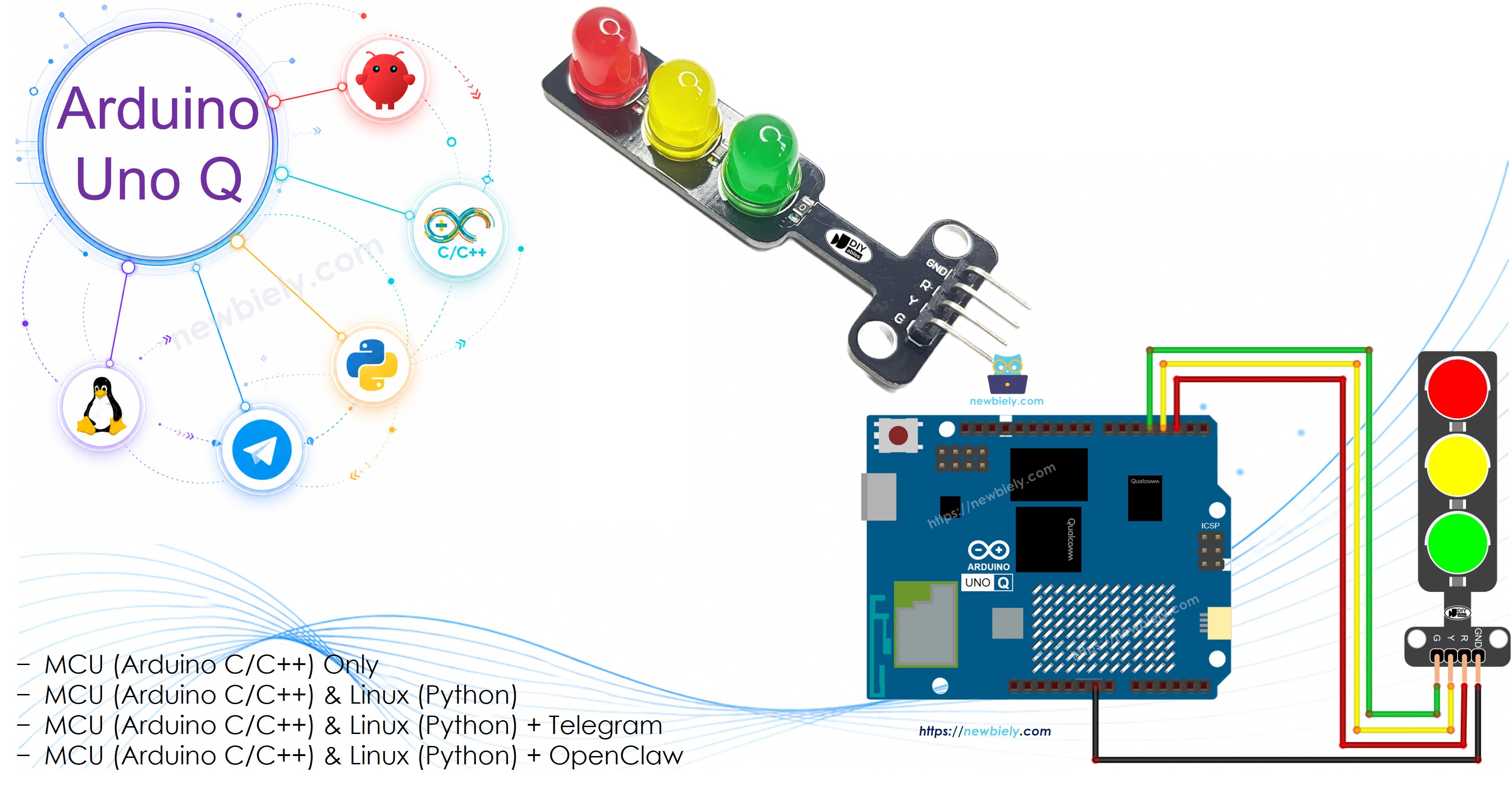
이 자습서에서는 Arduino UNO Q를 사용하여 신호등 모듈을 제어하는 방법을 배웁니다. 간단한 delay() 기반 시퀀스부터 논-블로킹 millis() 버전까지 여러 코딩 방식을 다루고, 이후 Telegram을 통해 신호등의 점등 시간을 원격으로 제어할 수 있도록 프로젝트를 확장합니다.
이 자습서에서 배우게 될 내용:
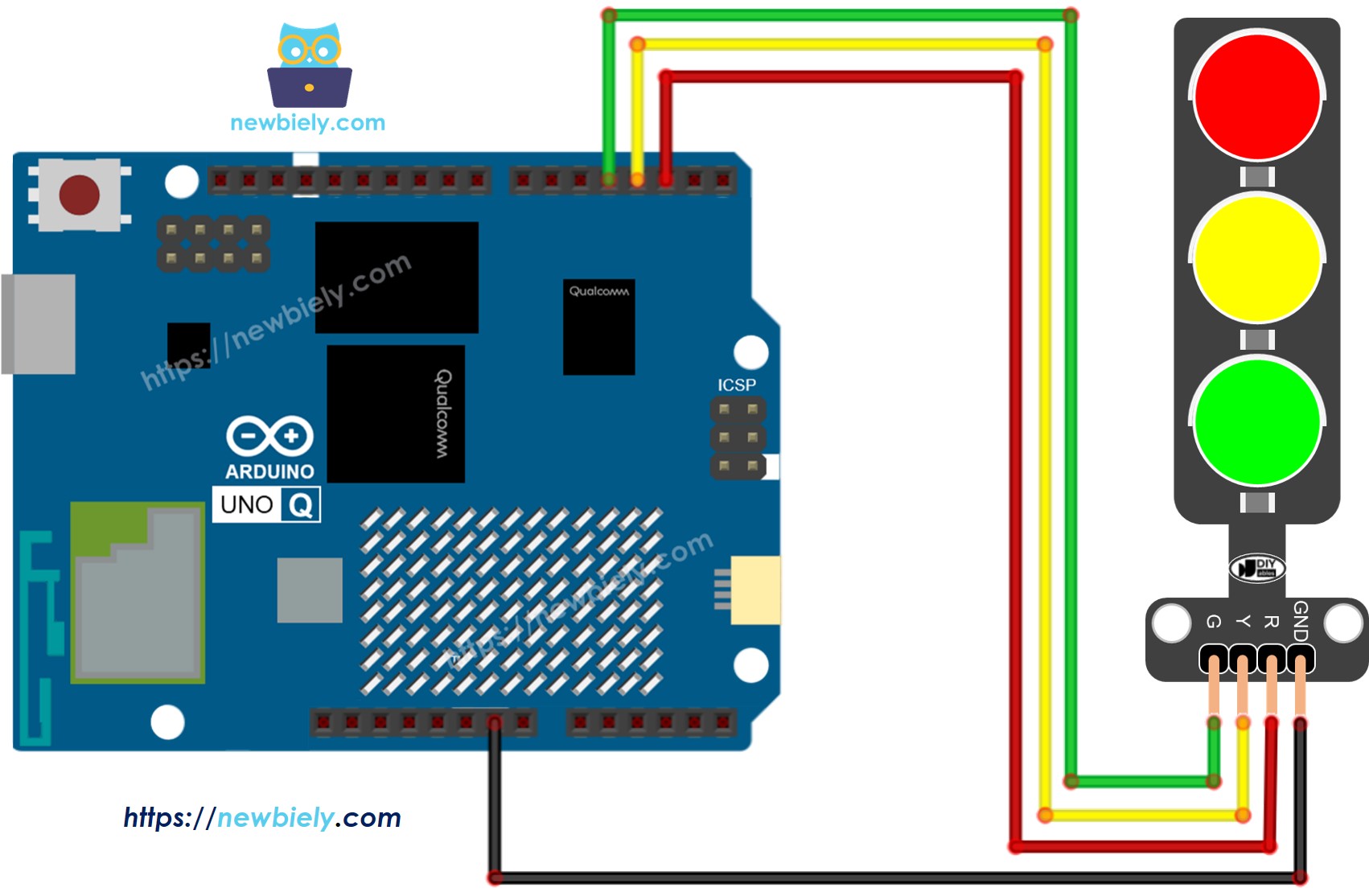
Arduino UNO Q에 신호등 모듈을 배선하는 방법
Arduino UNO Q MCU를 프로그래밍하여 빨강, 노랑, 초록 신호를 반복 제어하는 방법
digitalWrite(PIN_RED, HIGH); // turn RED ondigitalWrite(PIN_YELLOW, LOW); // turn YELLOW offdigitalWrite(PIN_GREEN, LOW); // turn GREEN offdelay(RED_TIME); // hold RED for the defined duration
MCU 코드 — 신호등(기본)
Arduino UNO Q는 두 개의 프로세서를 가지고 있습니다: STM32 MCU(실시간 하드웨어 제어 담당)와 Qualcomm MPU(Debian Linux 실행). 이 섹션에서는 STM32 MCU만 프로그래밍됩니다 — Linux 쪽은 유휴 상태입니다. 이후 섹션에서는 두 프로세서가 함께 작동하는 방법을 보여줍니다.
이 예제는 delay()를 사용하여 빨강, 노랑, 초록을 반복 제어합니다:
/* * 이 Arduino UNO Q 코드는 newbiely.kr 에서 개발되었습니다 * 이 Arduino UNO Q 코드는 어떠한 제한 없이 공개 사용을 위해 제공됩니다. * 상세한 지침 및 연결도에 대해서는 다음을 방문하세요: * https://newbiely.kr/tutorials/arduino-uno-q/arduino-uno-q-traffic-light */#define PIN_RED 2 // The Arduino UNO Q pin connected to R pin of traffic light module#define PIN_YELLOW 3 // The Arduino UNO Q pin connected to Y pin of traffic light module#define PIN_GREEN 4 // The Arduino UNO Q pin connected to G pin of traffic light module#define RED_TIME 4000 // RED time in millisecond#define YELLOW_TIME 4000 // YELLOW time in millisecond#define GREEN_TIME 4000 // GREEN time in millisecondvoidsetup() {pinMode(PIN_RED, OUTPUT);pinMode(PIN_YELLOW, OUTPUT);pinMode(PIN_GREEN, OUTPUT);}// the loop function runs over and over again forevervoidloop() {// red light ondigitalWrite(PIN_RED, HIGH); // turn ondigitalWrite(PIN_YELLOW, LOW); // turn offdigitalWrite(PIN_GREEN, LOW); // turn offdelay(RED_TIME); // keep red light on during a period of time// yellow light ondigitalWrite(PIN_RED, LOW); // turn offdigitalWrite(PIN_YELLOW, HIGH); // turn ondigitalWrite(PIN_GREEN, LOW); // turn offdelay(YELLOW_TIME); // keep yellow light on during a period of time// green light ondigitalWrite(PIN_RED, LOW); // turn offdigitalWrite(PIN_YELLOW, LOW); // turn offdigitalWrite(PIN_GREEN, HIGH); // turn ondelay(GREEN_TIME); // keep green light on during a period of time}
빠른 시작 단계
Arduino UNO Q 처음 사용? 계속하기 전에 아두이노 우노 Q 시작하기 자습서를 따라 개발 환경을 준비하세요.
모듈 배선: 배선도에 따라 신호등 모듈을 핀 2, 3, 4에 연결합니다.
연결: USB-C 케이블로 Arduino UNO Q를 컴퓨터에 연결합니다.
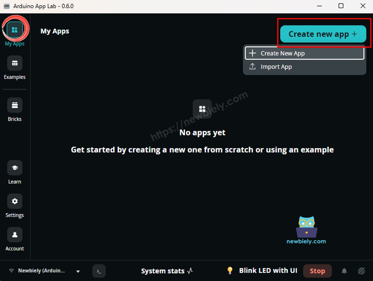
Arduino App Lab 열기: Arduino App Lab을 실행하고 Arduino UNO Q를 감지할 때까지 기다립니다.
새 앱 만들기:Create New App 버튼을 클릭합니다.
앱에 이름을 지정합니다. 예: DIYables_TrafficLight
Create를 클릭하여 확인합니다.
새 앱 내에 폴더와 파일 세트가 생성됩니다.
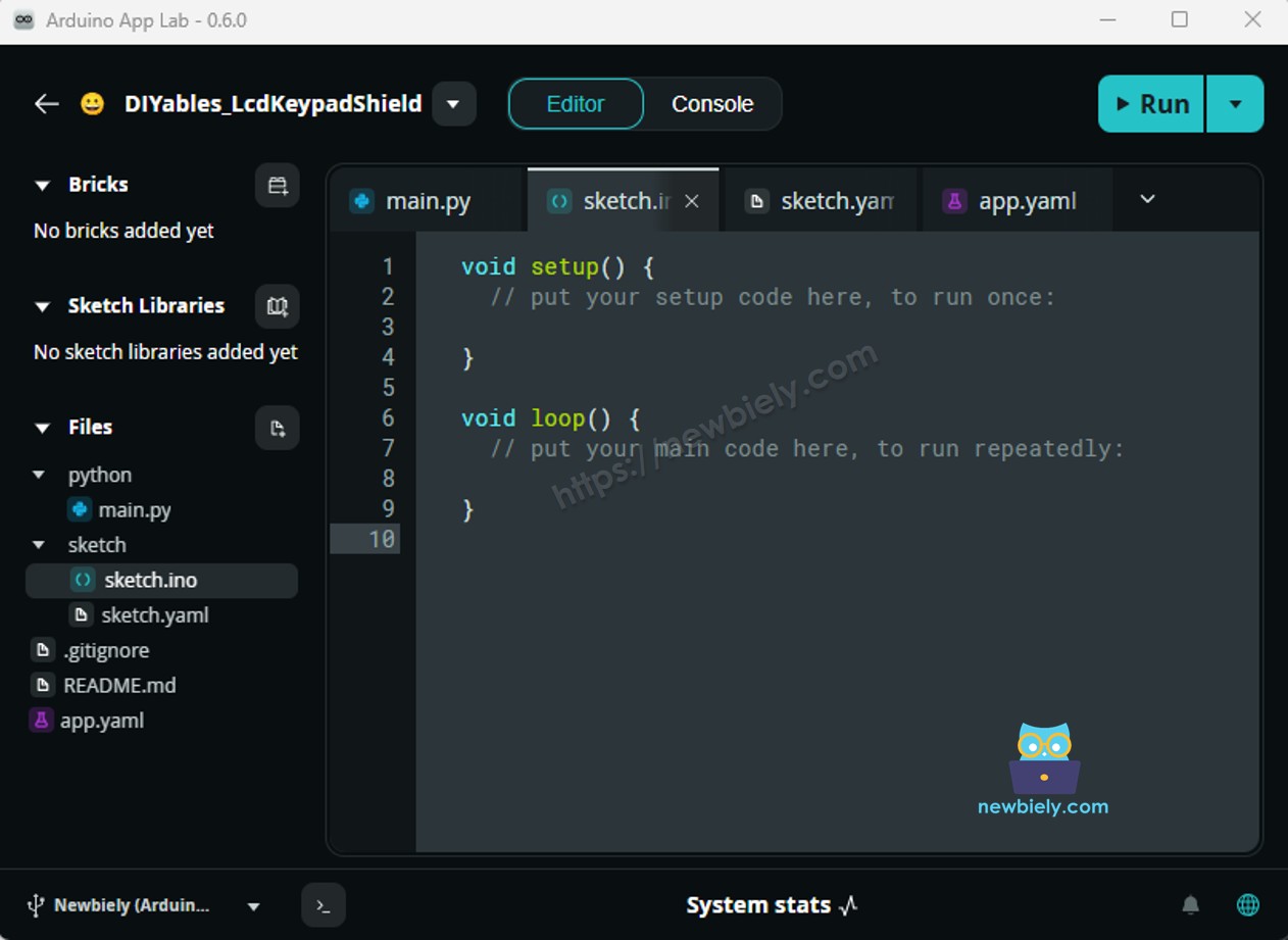
sketch/sketch.ino 파일을 찾습니다 — 이곳에 MCU 스케치를 붙여넣을 것입니다.
스케치 붙여넣기: 위의 MCU 코드를 복사하여 스케치 파일에 붙여넣습니다. 다른 파일은 기본값으로 유지합니다.
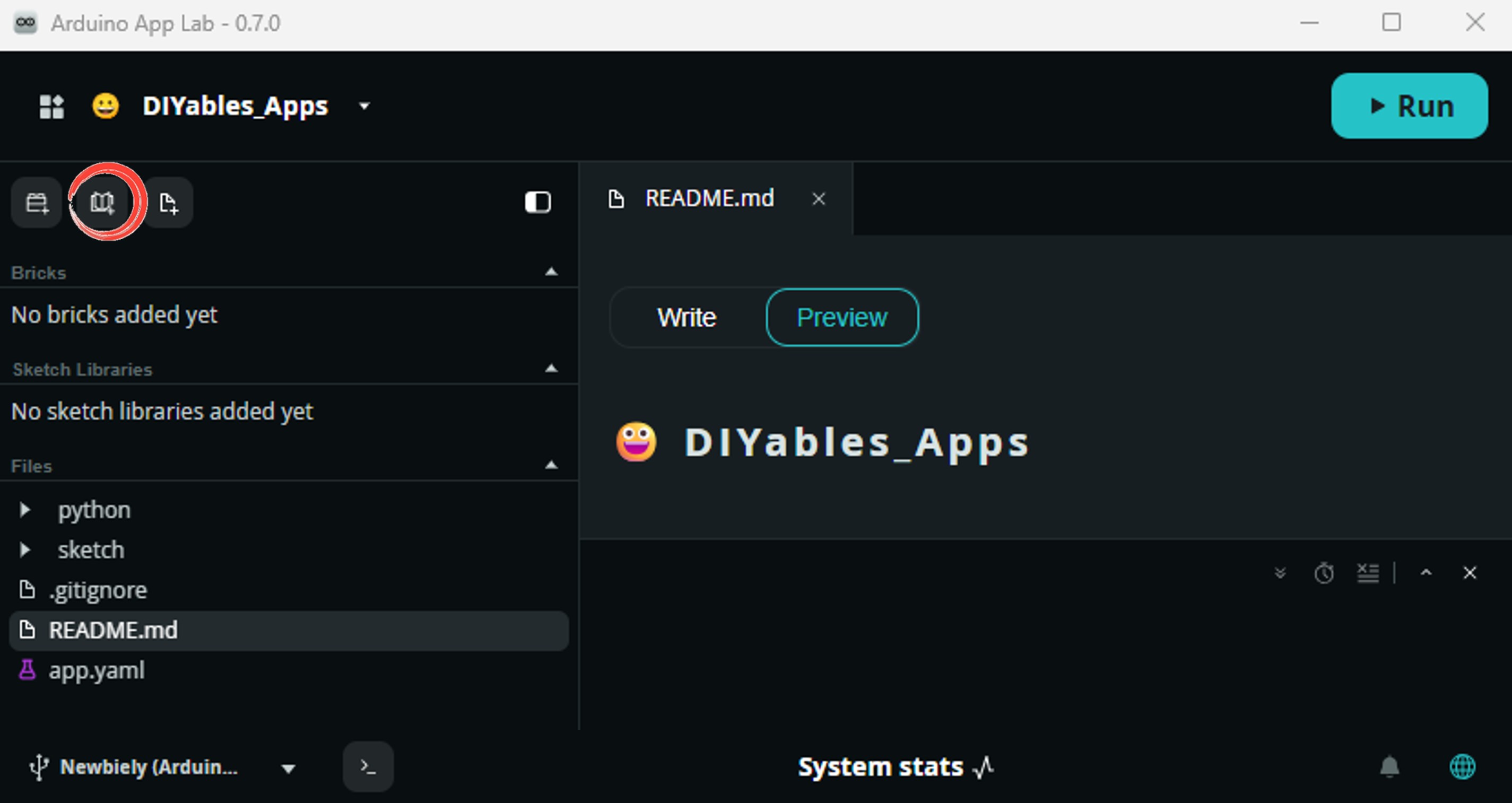
Install the library: Click the Add sketch library button (the open book icon with a + sign) in the left sidebar.
Search for Arduino_RouterBridge created by Arduino and click the Install button.
My Apps/DIYables Apps
Run
Bricks
No bricks added...
Sketch Libraries
No sketch libra...
Files
python
sketch
.gitignore
README.md
app.yaml
sketch.ino
Add sketch library
Arduino_RouterBridge
Arduino_RouterBridgeArduino
This library provides a simple RPC bridge for Arduino UNO Q boards, allowing communication between the board and other devices using MsgPack serialization.
0.4.1
Install
More Info
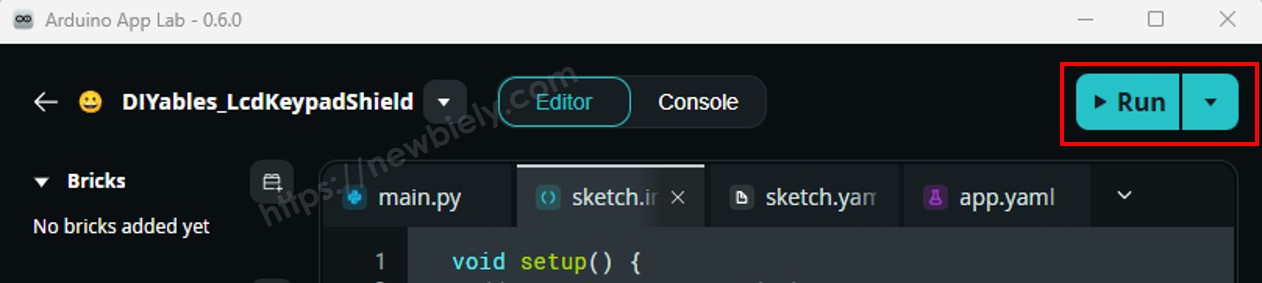
업로드: Arduino App Lab에서 Run 버튼을 클릭하여 컴파일하고 STM32에 업로드합니다.
모듈 확인: 신호등 모듈이 빨강 → 노랑 → 초록 → 빨강 순서로 반복되어야 합니다.
팁: 신호등 점등 시간은 위치 및 교차로 설계에 따라 다릅니다. RED_TIME, YELLOW_TIME, GREEN_TIME 값을 조정하여 원하는 동작에 맞춥니다.
MCU 코드 — 함수를 사용한 더 나은 버전
헬퍼 함수를 사용하면 코드가 더 짧아지고 관리하기 쉬워집니다:
/* * 이 Arduino UNO Q 코드는 newbiely.kr 에서 개발되었습니다 * 이 Arduino UNO Q 코드는 어떠한 제한 없이 공개 사용을 위해 제공됩니다. * 상세한 지침 및 연결도에 대해서는 다음을 방문하세요: * https://newbiely.kr/tutorials/arduino-uno-q/arduino-uno-q-traffic-light */#define PIN_RED 2 // The Arduino UNO Q pin connected to R pin of traffic light module#define PIN_YELLOW 3 // The Arduino UNO Q pin connected to Y pin of traffic light module#define PIN_GREEN 4 // The Arduino UNO Q pin connected to G pin of traffic light module#define RED_TIME 2000 // RED time in millisecond#define YELLOW_TIME 1000 // YELLOW time in millisecond#define GREEN_TIME 2000 // GREEN time in millisecond#define RED 0 // Index in array#define YELLOW 1 // Index in array#define GREEN 2 // Index in arrayconstint pins[] = { PIN_RED, PIN_YELLOW, PIN_GREEN };constint times[] = { RED_TIME, YELLOW_TIME, GREEN_TIME };voidsetup() {pinMode(PIN_RED, OUTPUT);pinMode(PIN_YELLOW, OUTPUT);pinMode(PIN_GREEN, OUTPUT);}// the loop function runs over and over again forevervoidloop() { trafic_light_on(RED);delay(times[RED]); // keep red light on during a period of time trafic_light_on(YELLOW);delay(times[YELLOW]); // keep yellow light on during a period of time trafic_light_on(GREEN);delay(times[GREEN]); // keep green light on during a period of time}void trafic_light_on(int light) {for (int i = RED; i <= GREEN; i++) {if (i == light)digitalWrite(pins[i], HIGH); // turn onelsedigitalWrite(pins[i], LOW); // turn off }}
팁:trafic_light_on(int light) 함수는 정확히 하나의 신호를 켜고 나머지는 끕니다 — 깔끔하고 재사용 가능합니다.
MCU 코드 — millis()를 사용한 논-블로킹 버전
delay() 함수는 대기하는 동안 다른 모든 코드를 블로킹합니다. 반응성 있는 프로그램(예: 신호등이 실행되는 동안 버튼이나 센서를 읽음)의 경우 millis()를 대신 사용합니다:
/* * 이 Arduino UNO Q 코드는 newbiely.kr 에서 개발되었습니다 * 이 Arduino UNO Q 코드는 어떠한 제한 없이 공개 사용을 위해 제공됩니다. * 상세한 지침 및 연결도에 대해서는 다음을 방문하세요: * https://newbiely.kr/tutorials/arduino-uno-q/arduino-uno-q-traffic-light */#define PIN_RED 2 // The Arduino UNO Q pin connected to R pin of traffic light module#define PIN_YELLOW 3 // The Arduino UNO Q pin connected to Y pin of traffic light module#define PIN_GREEN 4 // The Arduino UNO Q pin connected to G pin of traffic light module#define RED 0 // Index in array#define YELLOW 1 // Index in array#define GREEN 2 // Index in arrayconstint pins[] = { PIN_RED, PIN_YELLOW, PIN_GREEN };int times[] = { 2000, 1000, 2000 }; // RED, YELLOW, GREEN durations in msunsignedlong last_time = 0;int light = RED; // start with RED lightvoidsetup() {pinMode(PIN_RED, OUTPUT);pinMode(PIN_YELLOW, OUTPUT);pinMode(PIN_GREEN, OUTPUT); trafic_light_on(light); last_time = millis();}voidloop() {if ((millis() - last_time) > (unsignedlong)times[light]) { light++;if (light >= 3) light = RED; // new cycle trafic_light_on(light); last_time = millis(); }// TO DO: your other code here}void trafic_light_on(int light) {for (int i = RED; i <= GREEN; i++) {if (i == light)digitalWrite(pins[i], HIGH); // turn onelsedigitalWrite(pins[i], LOW); // turn off }}
팁:millis()를 사용하면 loop()에 버튼 또는 센서 코드를 신호등 로직과 함께 추가할 수 있습니다 — 서로를 블로킹하지 않고 동시에 실행됩니다.
Linux + MCU Bridge 프로그래밍
Arduino UNO Q는 함께 작동하는 두 개의 프로세서를 가지고 있습니다: MPU(Qualcomm, Debian Linux 실행)와 MCU(STM32, Arduino 스케치를 실행하는 Zephyr OS). 이들은 Arduino_RouterBridge 라이브러리를 사용하여 RPC를 통해 통신합니다 — 원시 시리얼 포트를 통하지 않습니다.
신호등 모듈은 MCU(STM32)에 연결됩니다 — STM32의 디지털 출력 핀에 배선됩니다. MCU는 논-블로킹 millis() 타이밍을 사용하여 신호를 반복 제어합니다.
MPU는 신호를 직접 제어할 수 없습니다 — Bridge.call()를 통해 MCU에 명령을 보내야 합니다. MCU는 등록된 Bridge.provide() 함수를 실행합니다.
MPU는 Wi-Fi를 가지고 있습니다 — MPU가 Wi-Fi를 갖춘 전체 Debian Linux를 실행하므로 Telegram 명령을 수신하고 신호 점등 시간을 원격으로 업데이트할 수 있습니다.
통신: Linux 쪽의 Bridge.call()은 MCU 쪽의 Bridge.provide() 함수를 호출합니다
⚠️ 예약됨:/dev/ttyHS1(Linux)과 Serial1(MCU)은 Arduino Router에서 사용됩니다 — 절대 직접 열지 마세요
간단히 말해: MPU가 타이밍 명령을 보냅니다 → MCU가 수신합니다 → MCU가 신호 점등 시간을 실시간으로 업데이트합니다.
MCU 스케치 — Bridge 타이밍 제어를 사용한 신호등:
/* * 이 Arduino UNO Q 코드는 newbiely.kr 에서 개발되었습니다 * 이 Arduino UNO Q 코드는 어떠한 제한 없이 공개 사용을 위해 제공됩니다. * 상세한 지침 및 연결도에 대해서는 다음을 방문하세요: * https://newbiely.kr/tutorials/arduino-uno-q/arduino-uno-q-traffic-light */#include"Arduino_RouterBridge.h"#define PIN_RED 2#define PIN_YELLOW 3#define PIN_GREEN 4#define RED 0#define YELLOW 1#define GREEN 2constint pins[] = { PIN_RED, PIN_YELLOW, PIN_GREEN };int times[] = { 2000, 1000, 2000 }; // RED, YELLOW, GREEN durations in msunsignedlong last_time = 0;int current_light = RED;const char* light_names[] = { "RED", "YELLOW", "GREEN" };void trafic_light_on(int light) {for (int i = RED; i <= GREEN; i++) {if (i == light)digitalWrite(pins[i], HIGH);elsedigitalWrite(pins[i], LOW); } Monitor.println("Light changed to: " + String(light_names[light]));}void set_timing(int red_ms, int yellow_ms, int green_ms) { times[RED] = red_ms; times[YELLOW] = yellow_ms; times[GREEN] = green_ms; Monitor.println("Timings updated: RED=" + String(red_ms) + "ms, YELLOW=" + String(yellow_ms) + "ms, GREEN=" + String(green_ms) + "ms");}void get_status() { Monitor.println("Current light: " + String(light_names[current_light]));}voidsetup() {pinMode(PIN_RED, OUTPUT);pinMode(PIN_YELLOW, OUTPUT);pinMode(PIN_GREEN, OUTPUT);Bridge.begin(); Monitor.begin();Bridge.provide("set_timing", set_timing);Bridge.provide("get_status", get_status); trafic_light_on(current_light); last_time = millis(); Monitor.println("Traffic Light Bridge ready");}voidloop() {if ((millis() - last_time) > (unsignedlong)times[current_light]) { current_light++;if (current_light >= 3) current_light = RED; trafic_light_on(current_light); last_time = millis(); }}
Python 스크립트(Arduino App Lab) — Linux에서 신호 점등 시간 제어:
/* * 이 Arduino UNO Q 코드는 newbiely.kr 에서 개발되었습니다 * 이 Arduino UNO Q 코드는 어떠한 제한 없이 공개 사용을 위해 제공됩니다. * 상세한 지침 및 연결도에 대해서는 다음을 방문하세요: * https://newbiely.kr/tutorials/arduino-uno-q/arduino-uno-q-traffic-light */from arduino.app_utils import *import timedef loop():print("Setting normal timing: RED=3s, YELLOW=1s, GREEN=3s") Bridge.call("set_timing", 3000, 1000, 3000) time.sleep(10)print("Setting fast timing: RED=1s, YELLOW=0.5s, GREEN=1s") Bridge.call("set_timing", 1000, 500, 1000) time.sleep(8)print("Restoring default timing: RED=2s, YELLOW=1s, GREEN=2s") Bridge.call("set_timing", 2000, 1000, 2000)App.run(user_loop=loop)
참고: MCU 스케치에서 Bridge.begin()이 호출되고 스케치가 업로드된 후 Linux 쪽에서 Python 스크립트를 실행해야 합니다.
⚠️ 경고:/dev/ttyHS1(Linux) 또는 Serial1(MCU)을 코드에서 직접 열지 마세요 — 이들은 Arduino Router에서 예약되어 있으며 접근하면 Bridge가 손상됩니다.
빠른 시작 단계
MCU 스케치 업로드: Arduino App Lab을 열고 새 앱을 만들고, 위의 Bridge MCU 스케치를 sketch/sketch.ino에 붙여넣고, 기본 라이브러리를 유지한 후(추가 라이브러리 필요 없음) Run을 클릭합니다.
Python 스크립트 추가: 위의 Python 코드를 같은 앱의 Python 탭에 붙여넣습니다.