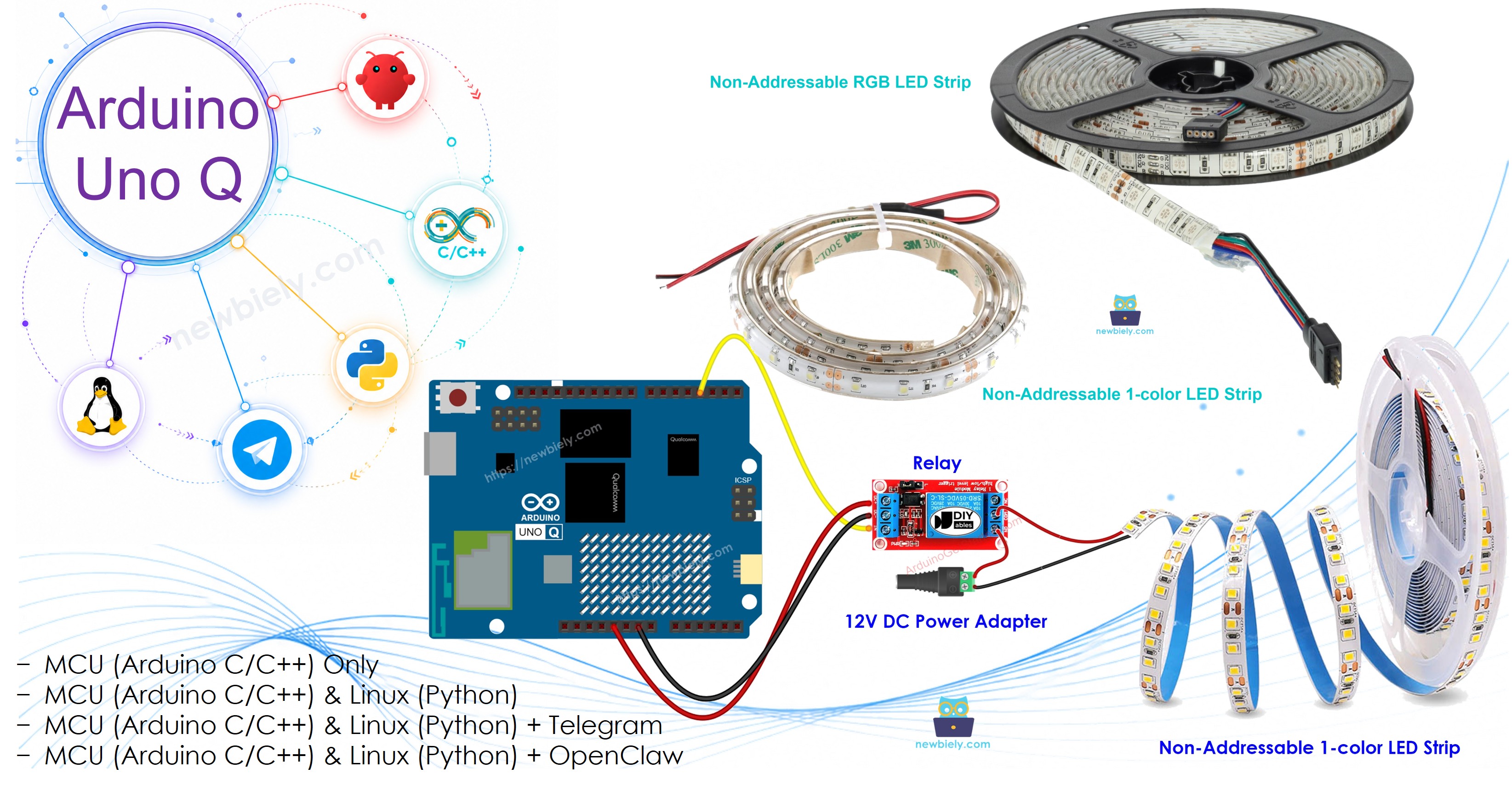
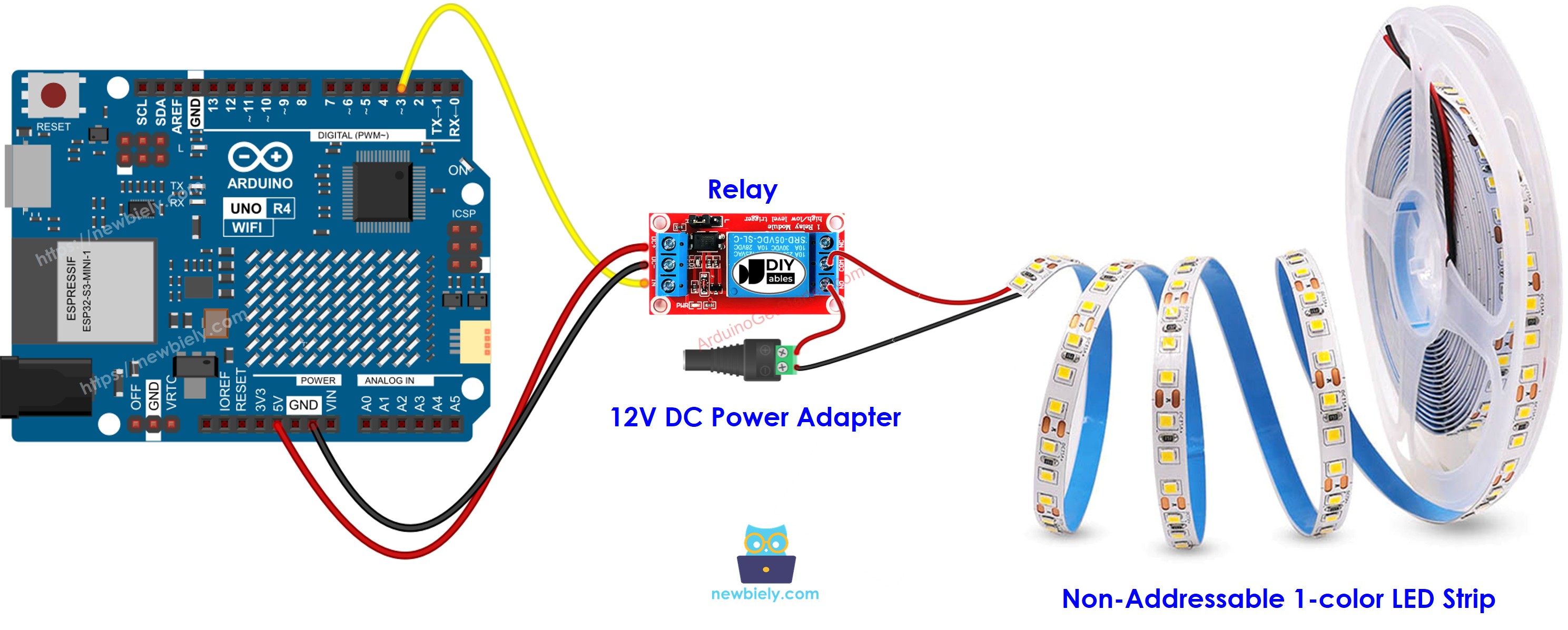
Arduino UNO Q로 12V LED 스트립을 제어하는 방법을 배우세요. LED 스트립은 12V DC에서 작동하므로 Arduino 핀에 직접 연결할 수 없습니다 — 릴레이 모듈이 중간 역할을 합니다. 이 튜토리얼은 단색 및 RGB LED 스트립, Bridge 모드로 소프트웨어 색상 제어, Telegram 원격 명령을 다룹니다.
이 튜토리얼에서 배울 내용:
12V LED 스트립이 작동하는 방식 및 릴레이가 필요한 이유
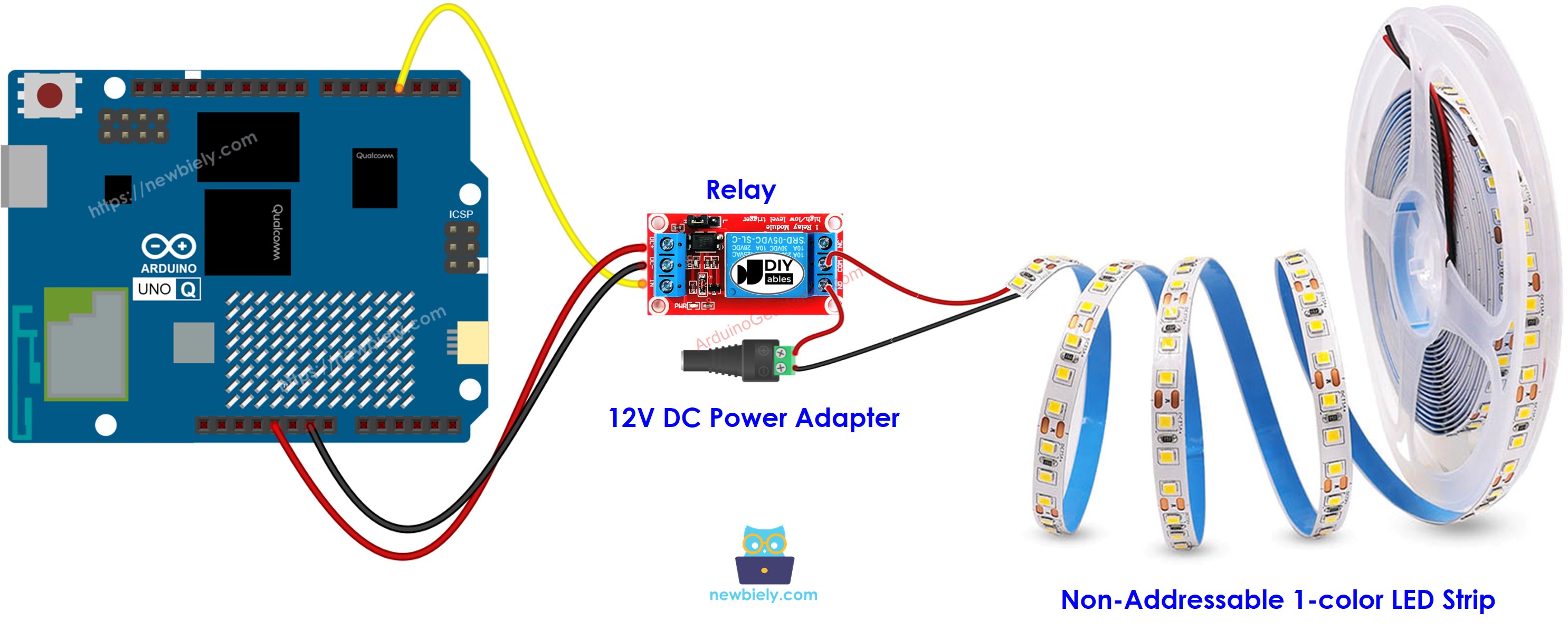
릴레이를 통해 단색 LED 스트립을 Arduino UNO Q에 연결하는 방법
3개의 릴레이를 통해 RGB LED 스트립을 Arduino UNO Q에 연결하는 방법
Bridge 및 Python을 사용하여 Arduino UNO Q에서 RGB 색상을 제어하는 방법
Arduino UNO Q에서 Telegram을 통해 LED 스트립 색상을 원격으로 제어하는 방법
Arduino UNO Q에서 LED 스트립과 함께 OpenClaw를 사용하는 방법
※ 주의:
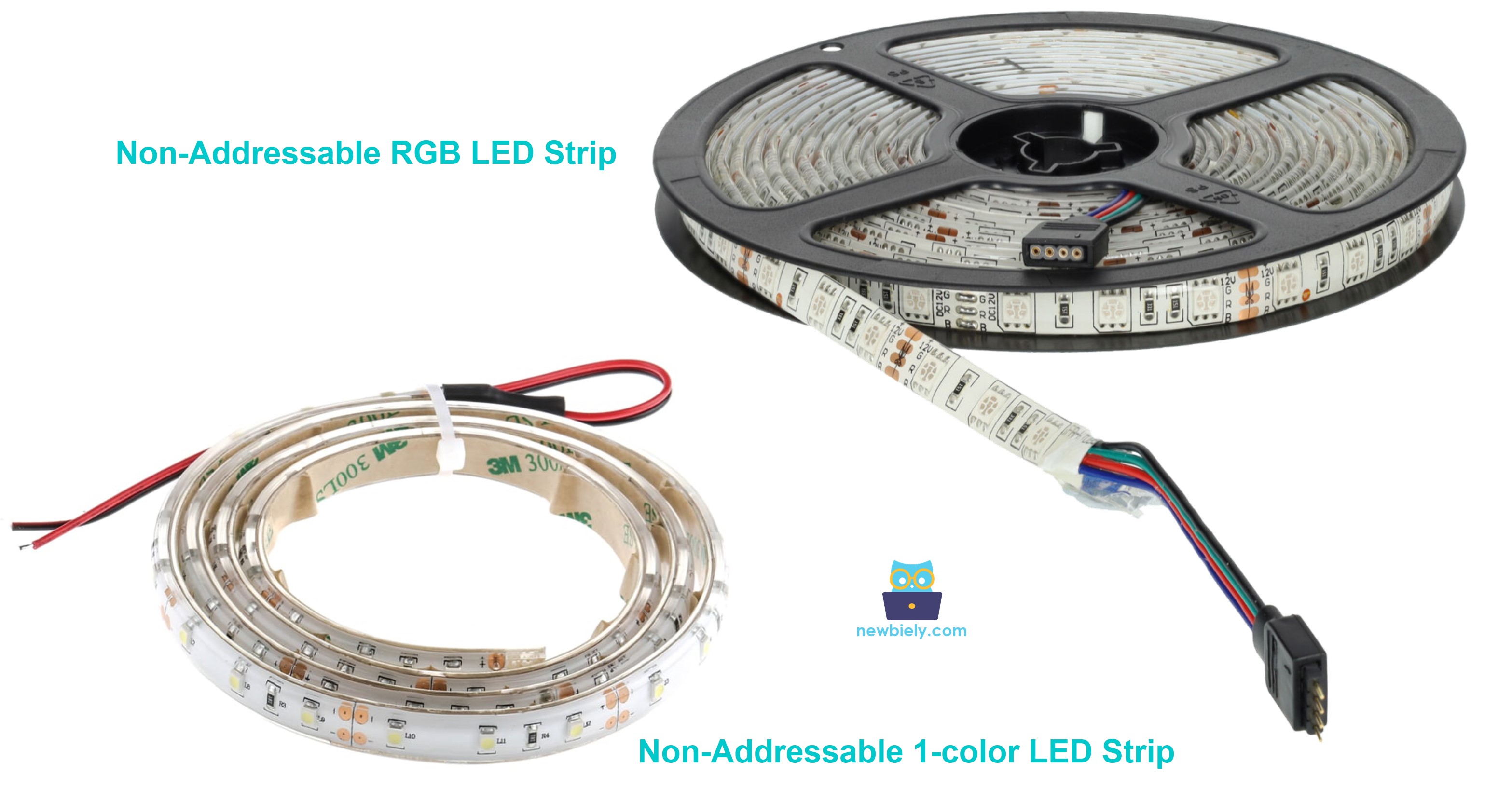
이 튜토리얼은 논 어드레서블 LED 스트립(모든 LED가 함께 변합니다)을 다룹니다. 개별 어드레싱 가능한 LED 스트립은 NeoPixel 및 WS2812B 튜토리얼을 참조하세요.
Qualcomm MPU는 Wi-Fi가 포함된 Debian Linux를 실행합니다 — 이 섹션에서는 MCU만 프로그래밍됩니다. 이후 섹션에서는 Bridge를 통해 두 프로세서가 함께 작동하는 방법을 보여줍니다.
/* * 이 Arduino UNO Q 코드는 newbiely.kr 에서 개발되었습니다 * 이 Arduino UNO Q 코드는 어떠한 제한 없이 공개 사용을 위해 제공됩니다. * 상세한 지침 및 연결도에 대해서는 다음을 방문하세요: * https://newbiely.kr/tutorials/arduino-uno-q/arduino-uno-q-led-strip */// Controls a 12V single-color LED strip via a relay// Relay HIGH = LED strip ON, LOW = LED strip OFF#define RELAY_PIN 3 // The Arduino UNO Q MCU pin connected to the relay for the LED stripvoidsetup() {Serial.begin(9600);pinMode(RELAY_PIN, OUTPUT);digitalWrite(RELAY_PIN, LOW); // ensure strip is off on startup}voidloop() {Serial.println("The LED strip is turned on");digitalWrite(RELAY_PIN, HIGH);delay(5000);Serial.println("The LED strip is turned off");digitalWrite(RELAY_PIN, LOW);delay(5000);}
/* * 이 Arduino UNO Q 코드는 newbiely.kr 에서 개발되었습니다 * 이 Arduino UNO Q 코드는 어떠한 제한 없이 공개 사용을 위해 제공됩니다. * 상세한 지침 및 연결도에 대해서는 다음을 방문하세요: * https://newbiely.kr/tutorials/arduino-uno-q/arduino-uno-q-led-strip */// Controls a 12V RGB LED strip via 3 relays (one per color channel)// HIGH = color channel ON, LOW = color channel OFF#define RED_PIN 6 // The Arduino UNO Q MCU pin connected to the relay for the RED channel#define GREEN_PIN 7 // The Arduino UNO Q MCU pin connected to the relay for the GREEN channel#define BLUE_PIN 5 // The Arduino UNO Q MCU pin connected to the relay for the BLUE channelvoid setColor(bool r, bool g, bool b) {digitalWrite(RED_PIN, r ? HIGH : LOW);digitalWrite(GREEN_PIN, g ? HIGH : LOW);digitalWrite(BLUE_PIN, b ? HIGH : LOW);}voidsetup() {Serial.begin(9600);pinMode(RED_PIN, OUTPUT);pinMode(GREEN_PIN, OUTPUT);pinMode(BLUE_PIN, OUTPUT); setColor(false, false, false); // all off on startup}voidloop() {Serial.println("Red"); setColor(true, false, false);delay(2000);Serial.println("Green"); setColor(false, true, false);delay(2000);Serial.println("Blue"); setColor(false, false, true);delay(2000);Serial.println("Yellow"); setColor(true, true, false);delay(2000);Serial.println("Magenta"); setColor(true, false, true);delay(2000);Serial.println("Cyan"); setColor(false, true, true);delay(2000);Serial.println("White"); setColor(true, true, true);delay(2000);Serial.println("Off"); setColor(false, false, false);delay(2000);}
App Lab 콘솔 출력
DIYables_Apps
Stop
sketch.ino
1#include"Arduino_RouterBridge.h"
Serial Monitor
Python
Message (Enter to send a message to "Newbiely" on usb(2820070321))
New Line
9600 baud
[2026-04-29 09:00:01] Red
[2026-04-29 09:00:03] Green
[2026-04-29 09:00:05] Blue
[2026-04-29 09:00:07] Yellow
[2026-04-29 09:00:09] Magenta
[2026-04-29 09:00:11] Cyan
[2026-04-29 09:00:13] White
[2026-04-29 09:00:15] Off
Bridge: Linux + MCU
이 섹션에서는 Bridge를 통해 Linux 측에서 Arduino UNO Q의 두 프로세서를 사용하여 RGB LED 스트립 색상을 제어하는 방법을 보여줍니다:
3개 릴레이는 MCU로 제어됩니다 — MCU는 Bridge를 통해 set_color() 함수를 노출합니다
MPU는 릴레이 핀을 직접 제어할 수 없습니다 — LED 스트립 색상을 변경하도록 Bridge를 호출합니다
MPU는 Wi-Fi가 있습니다 — 전체 Debian Linux를 실행하면서 Telegram 색상 명령을 수락하고 즉시 LED 스트립을 업데이트할 수 있습니다
Arduino_RouterBridge는 RPC 통신을 두 프로세서 간에 활성화합니다
⚠️ /dev/ttyHS1 (Linux) 및 Serial1 (MCU)은 라우터에서 예약됨 — 사용자 코드에서 이를 열지 마세요
MCU 코드 (Bridge)
/* * 이 Arduino UNO Q 코드는 newbiely.kr 에서 개발되었습니다 * 이 Arduino UNO Q 코드는 어떠한 제한 없이 공개 사용을 위해 제공됩니다. * 상세한 지침 및 연결도에 대해서는 다음을 방문하세요: * https://newbiely.kr/tutorials/arduino-uno-q/arduino-uno-q-led-strip */#include"Arduino_RouterBridge.h"#define RED_PIN 6 // The Arduino UNO Q MCU pin connected to the relay for the RED channel#define GREEN_PIN 7 // The Arduino UNO Q MCU pin connected to the relay for the GREEN channel#define BLUE_PIN 5 // The Arduino UNO Q MCU pin connected to the relay for the BLUE channelString current_color = "off";void applyColor(bool r, bool g, bool b) {digitalWrite(RED_PIN, r ? HIGH : LOW);digitalWrite(GREEN_PIN, g ? HIGH : LOW);digitalWrite(BLUE_PIN, b ? HIGH : LOW);}String set_color(String color) { color.toLowerCase(); color.trim();if (color == "red") { applyColor(true, false, false); current_color = "red"; }elseif (color == "green") { applyColor(false, true, false); current_color = "green"; }elseif (color == "blue") { applyColor(false, false, true); current_color = "blue"; }elseif (color == "yellow") { applyColor(true, true, false); current_color = "yellow"; }elseif (color == "magenta") { applyColor(true, false, true); current_color = "magenta"; }elseif (color == "cyan") { applyColor(false, true, true); current_color = "cyan"; }elseif (color == "white") { applyColor(true, true, true); current_color = "white"; }elseif (color == "off") { applyColor(false, false, false); current_color = "off"; }else { return"unknown color: " + color; } Monitor.println("Color set to: " + current_color);return"ok:" + current_color;}String get_state(String arg) {return current_color;}voidsetup() {Bridge.begin(); Monitor.begin();pinMode(RED_PIN, OUTPUT);pinMode(GREEN_PIN, OUTPUT);pinMode(BLUE_PIN, OUTPUT); applyColor(false, false, false);Bridge.provide_safe("set_color", set_color);Bridge.provide("get_state", get_state); Monitor.println("Arduino UNO Q RGB LED Strip Bridge ready");}voidloop() {}
Python 코드 (Bridge)
/* * 이 Arduino UNO Q 코드는 newbiely.kr 에서 개발되었습니다 * 이 Arduino UNO Q 코드는 어떠한 제한 없이 공개 사용을 위해 제공됩니다. * 상세한 지침 및 연결도에 대해서는 다음을 방문하세요: * https://newbiely.kr/tutorials/arduino-uno-q/arduino-uno-q-led-strip */from arduino.app_utils import *import timeCOLORS = ["red", "green", "blue", "yellow", "magenta", "cyan", "white", "off"]def loop():for color in COLORS: result = Bridge.call("set_color", color) state = Bridge.call("get_state")print(f"Set color: {color} → result: {result} state: {state}") time.sleep(2)App.run(user_loop=loop)
빠른 단계
연결: RGB 배선 다이어그램에 표시된 대로 3개의 릴레이를 통해 RGB LED 스트립을 Arduino UNO Q에 연결합니다.
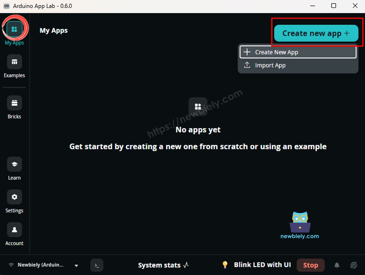
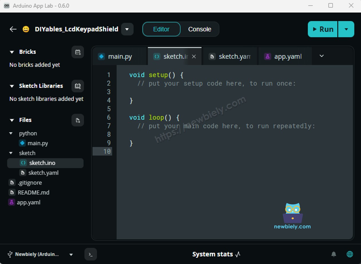
Arduino App Lab 열기하고 LedStripBridge라는 새 앱을 만듭니다.
MCU 스케치를 붙여넣기sketch/sketch.ino에 붙여넣습니다.
Python 코드를 붙여넣기 Python 파일에 붙여넣습니다.
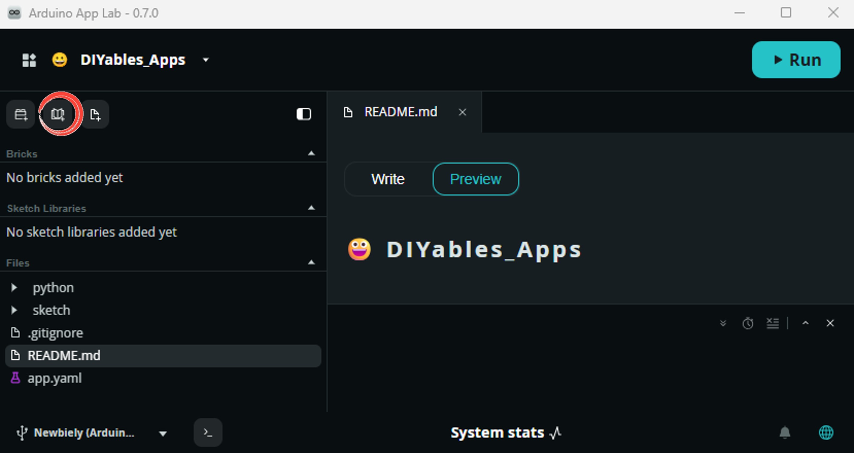
Install the library: Click the Add sketch library button (the open book icon with a + sign) in the left sidebar.
Search for Arduino_RouterBridge created by Arduino and click the Install button.
My Apps/DIYables Apps
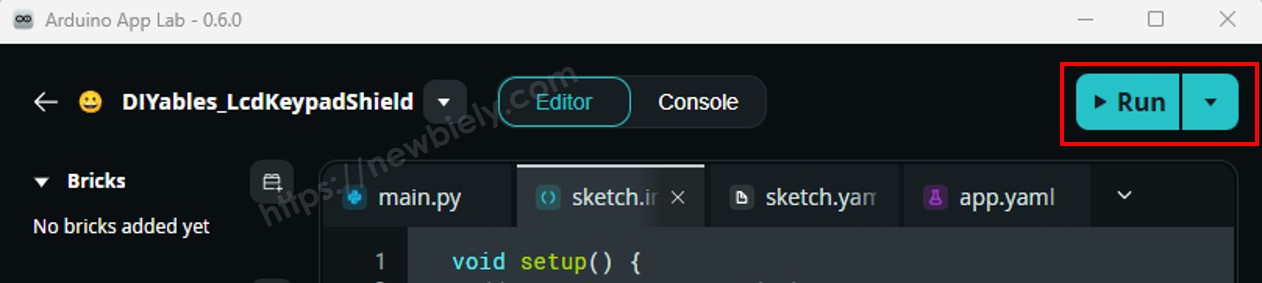
Run
Bricks
No bricks added...
Sketch Libraries
No sketch libra...
Files
python
sketch
.gitignore
README.md
app.yaml
sketch.ino
Add sketch library
Arduino_RouterBridge
Arduino_RouterBridgeArduino
This library provides a simple RPC bridge for Arduino UNO Q boards, allowing communication between the board and other devices using MsgPack serialization.
0.4.1
Install
More Info
업로드: Run 버튼을 클릭합니다. LED 스트립이 모든 색상을 순환하는 것을 관찰합니다.
App Lab 콘솔 출력
DIYables_Apps
Stop
sketch.ino
1#include"Arduino_RouterBridge.h"
Serial Monitor
Python
Message (Enter to send a message to "Newbiely" on usb(2820070321))
New Line
9600 baud
[2026-04-29 09:00:01] Arduino UNO Q RGB LED Strip Bridge ready
[2026-04-29 09:00:02] Color set to: red
[2026-04-29 09:00:04] Color set to: green
[2026-04-29 09:00:06] Color set to: blue
DIYables_Apps
Stop
sketch.ino
1#include"Arduino_RouterBridge.h"
Serial Monitor
Python
[2026-04-29 09:00:02] Set color: red → result: ok:red state: red
[2026-04-29 09:00:04] Set color: green → result: ok:green state: green
[2026-04-29 09:00:06] Set color: blue → result: ok:blue state: blue
[2026-04-29 09:00:08] Set color: yellow → result: ok:yellow state: yellow
[2026-04-29 09:00:10] Set color: magenta → result: ok:magenta state: magenta
[2026-04-29 09:00:12] Set color: cyan → result: ok:cyan state: cyan
[2026-04-29 09:00:14] Set color: white → result: ok:white state: white
[2026-04-29 09:00:16] Set color: off → result: ok:off state: off
Telegram
Telegram에서 RGB LED 스트립 색상을 원격으로 제어합니다 — Arduino UNO Q의 LED 스트립 색상을 즉시 변경하려면 Telegram에 /color red, /color blue 또는 지원하는 색상 이름을 보냅니다.
MCU 스케치: 이전 Bridge 섹션에서 동일한 MCU 스케치를 유지합니다.
Python 코드 (Telegram)
/* * 이 Arduino UNO Q 코드는 newbiely.kr 에서 개발되었습니다 * 이 Arduino UNO Q 코드는 어떠한 제한 없이 공개 사용을 위해 제공됩니다. * 상세한 지침 및 연결도에 대해서는 다음을 방문하세요: * https://newbiely.kr/tutorials/arduino-uno-q/arduino-uno-q-led-strip */from arduino.app_utils import *import requestsimport timeTELEGRAM_BOT_TOKEN = "YOUR_TELEGRAM_BOT_TOKEN"CHAT_ID = "YOUR_CHAT_ID"last_update_id = 0COLORS = ["red", "green", "blue", "yellow", "magenta", "cyan", "white", "off"]def get_updates():global last_update_id url = f"https://api.telegram.org/bot{TELEGRAM_BOT_TOKEN}/getUpdates" params = {"offset": last_update_id + 1, "timeout": 5}try: response = requests.get(url, params=params, timeout=10) data = response.json()if data["ok"]:return data["result"]exceptExceptionas e:print(f"Error getting updates: {e}")return []def send_message(chat_id, text): url = f"https://api.telegram.org/bot{TELEGRAM_BOT_TOKEN}/sendMessage" payload = {"chat_id": chat_id, "text": text}try: requests.post(url, data=payload, timeout=10)exceptExceptionas e:print(f"Error sending message: {e}")def loop(): updates = get_updates()for update in updates: last_update_id = update["update_id"]if"message"notin update:continue message = update["message"] chat_id = message["chat"]["id"] text = message.get("text", "").strip()print(f"Received: {text}")if text == "/start": send_message(chat_id,"Arduino UNO Q RGB LED Strip Bot\n""/color <name> - Set color (red, green, blue, yellow, magenta, cyan, white, off)\n""/state - Current LED strip color\n""Example: /color red")elif text.startswith("/color"): parts = text.split()iflen(parts) < 2: send_message(chat_id, "Usage: /color <name>\nColors: " + ", ".join(COLORS))else: color = parts[1].lower()if color notin COLORS: send_message(chat_id, f"Unknown color: {color}\nAvailable: " + ", ".join(COLORS))else: result = Bridge.call("set_color", color) state = Bridge.call("get_state") send_message(chat_id, f"💡 LED strip color set to: {state}")elif text == "/state": state = Bridge.call("get_state") send_message(chat_id, f"Current LED strip color: {state}")else: send_message(chat_id, "Unknown command. Send /start for help.") time.sleep(0.3)App.run(user_loop=loop)
빠른 단계
YOUR_TELEGRAM_BOT_TOKEN을 BotFather에서 실제 봇 토큰으로 바꿉니다.
YOUR_CHAT_ID를 Telegram 채팅 ID로 바꿉니다.
이 Python 코드를 앱의 Python 파일에 붙여넣습니다 (동일한 MCU 스케치 유지).
Run 버튼을 클릭합니다 — Telegram에서 /color red를 보내 LED 스트립 색상을 변경합니다.
App Lab 콘솔 출력
DIYables_Apps
Stop
sketch.ino
1#include"Arduino_RouterBridge.h"
Serial Monitor
Python
[2026-04-29 09:10:01] Waiting for Telegram messages...
[2026-04-29 09:10:05] Received: /color red
[2026-04-29 09:10:08] Received: /color cyan
[2026-04-29 09:10:12] Received: /state
[2026-04-29 09:10:15] Received: /color off
Telegram12:45
Welcome to Telegram!
ArduinoBot10:19
Chatting with Arduino...
BotFatherYesterday
Your bot has been created.
ArduinoBot
bot
Today
/color red
10:15 AM✓✓
💡 LED strip color set to: red
10:16 AM
/color cyan
10:17 AM✓✓
💡 LED strip color set to: cyan
10:18 AM
/state
10:19 AM✓✓
Current LED strip color: cyan
10:20 AM
/color off
10:21 AM✓✓
💡 LED strip color set to: off
10:22 AM
OpenClaw
You can adapt the OpenClaw to this tutorial by refering the instruction on 아두이노 우노 Q - OpenClaw Tutorial
프로젝트 아이디어
Arduino UNO Q와 LED 스트립으로 많은 유용한 프로젝트를 만들 수 있습니다:
Telegram 분위기 조명: 언제든지 Telegram에서 방의 RGB LED 스트립 색상을 제어합니다 — 편안한 저녁 분위기를 위해 /color blue를 보내거나 작업 모드를 위해 /color white를 보냅니다
알림 조명: 가스 센서 튜토리얼과 결합합니다 — 가스가 감지되면 Python은 Bridge를 통해 LED 스트립을 빨강(경고)으로 설정합니다; 해제되면 흰색(정상)으로 돌아갑니다
일정 기반 조명: Python의 time 모듈을 사용하여 Telegram 입력 없이 시간에 따라 LED 스트립 색상을 자동으로 변경합니다 — 저녁에는 따뜻한 흰색, 아침에는 시원한 흰색
음악 반응형 조명: 사운드 센서와 결합합니다 — 사운드 센서가 비트를 감지하면 Python은 빠르게 색상을 순환하여 음악 반응형 조명 효과를 만듭니다
상태 표시기 패널: LED 스트립을 서버실 또는 작업실의 상태 표시기로 사용합니다 — 초록색 = 모든 시스템 정상, 노란색 = 경고, 빨강색 = 심각한 경고 — Bridge에서 모니터링 스크립트로 제어됨
도전해 보세요
Arduino UNO Q의 LED 스트립으로 더 나아가실 준비가 되셨나요? 다음 도전 과제를 시도해 보세요:
쉬움:/blink <color> <count> Telegram 명령을 추가합니다. 선택한 색상으로 LED 스트립을 지정된 횟수만큼 깜박입니다. 깜박임당 500ms 켜짐 및 500ms 꺼짐입니다.
중간: 부드러운 색상 순환 모드 구현: Telegram을 통해 /mode cycle이 전송되면 Python은 3초 일시 중지와 함께 모든 7개 색상을 순환하는 루프에 들어갑니다. /mode stop은 루프를 빠져나와 스트립을 끕니다.
어려움: 일출 알람 빌드: 사용자가 정의한 시간 (Telegram 명령 /alarm HH:MM을 통해 설정)에 Python은 LED 스트립을 꺼짐 → 빨강색 → 노란색 → 흰색으로 10분에 걸쳐 천천히 전환하여 자연 일출 깨우기 경험을 시뮬레이션합니다.