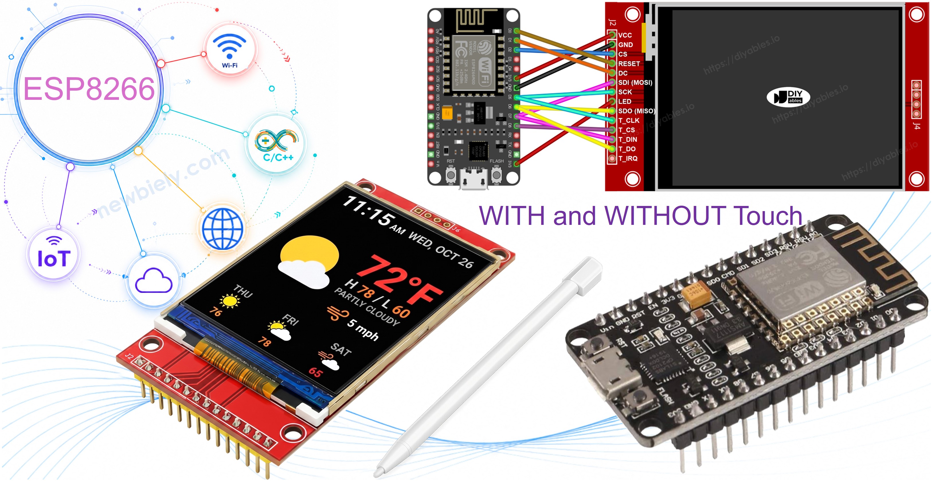
ESP8266 ILI9341 ILI9488 ST7789 TFT LCD 터치 디스플레이 SPI 인터페이스
이 가이드는 ESP8266 NodeMCU 보드에 SPI TFT 디스플레이를 연결하는 실용적인 안내입니다. ESP8266은 80-160MHz로 동작하는 소형 Wi-Fi 지원 마이크로컨트롤러로 3.3V에서 동작합니다. 하드웨어 SPI 버스는 GPIO13(MOSI), GPIO14(SCK), GPIO12(MISO)에 있으며 — Arduino 보드처럼 D11/D13/D12로 표시되지 않습니다.
다루는 내용:
- ESP8266 NodeMCU에서 올바른 SPI 핀 식별하기.
- 3.3V SPI TFT 디스플레이 안전하게 배선하기.
- 도형 및 그래픽 그리기.
- 텍스트 및 숫자 표시하기.
- 프로그램 메모리(PROGMEM)에서 비트맵 이미지 그리기.
- SD 카드에서 로드한 비트맵 이미지 그리기.
- 사용자 정의 외부 폰트로 텍스트 렌더링하기.
- XPT2046 컨트롤러에서 터치 좌표 읽기.
- 터치 드래그로 화면에 그리기.
- 인터랙티브 터치 버튼 만들기.
- 터치 스크린 보정하기.
- 보조 또는 사용자 정의 SPI 버스 사용하기.
이 튜토리얼은 ILI9341, ILI9488 또는 ST7789 컨트롤러 칩으로 구동되는 1.3, 1.54, 2.2, 2.4, 2.8, 3.2, 3.5인치 패널에서 터치 및 비터치 SPI TFT LCD 디스플레이를 모두 지원합니다.
필요한 하드웨어
| 1 | × | ESP8266 NodeMCU development board | 쿠팡 | 아마존 | |
| 1 | × | USB Cable (Type-A to Micro-B) | 아마존 | |
| 1 | × | SPI TFT display module | 쿠팡 | 아마존 | |
| 1 | × | 점퍼케이블 | 쿠팡 | 아마존 | |
| 1 | × | (추천) ESP8266용 스크루 터미널 확장 보드 | 쿠팡 | 아마존 |
SPI TFT 디스플레이
SPI TFT 모듈은 전용 드라이버 IC를 사용하여 고속 SPI 링크를 통해 드로잉 명령을 수신하고 LCD 픽셀을 제어합니다. 세 가지 드라이버가 지원됩니다:
- ILI9341 - 16비트 RGB565 컬러, 최대 40MHz SPI.
- ILI9488 - SPI를 통한 18비트 RGB666 컬러, 최대 24MHz.
- ST7789 - 16비트 RGB565 컬러, 최대 40MHz SPI.
권장 사항: 아직 디스플레이를 구매하지 않으셨다면 ST7789 드라이버를 권장합니다. 광범위하게 구할 수 있고 최대 40MHz SPI 속도로 동작하며 새 프로젝트에 가장 간단한 선택입니다.
드로잉 호출은 Adafruit GFX API를 통해 이루어집니다: 도형, 텍스트, 폰트, 비트맵이 모두 사용 가능합니다.
참고: ESP8266은 3.3V에서 동작합니다. TFT VCC를 3.3V 핀에 연결하세요. 5V를 인가하면 보드가 손상됩니다.
부팅 핀 경고: GPIO0, GPIO2, GPIO15는 ESP8266의 부팅 모드에 영향을 줍니다. 업로드 실패를 방지하려면 TFT CS, DC, RST에 이 핀들을 사용하지 마세요. GPIO4, GPIO5, GPIO16은 안전한 선택입니다.
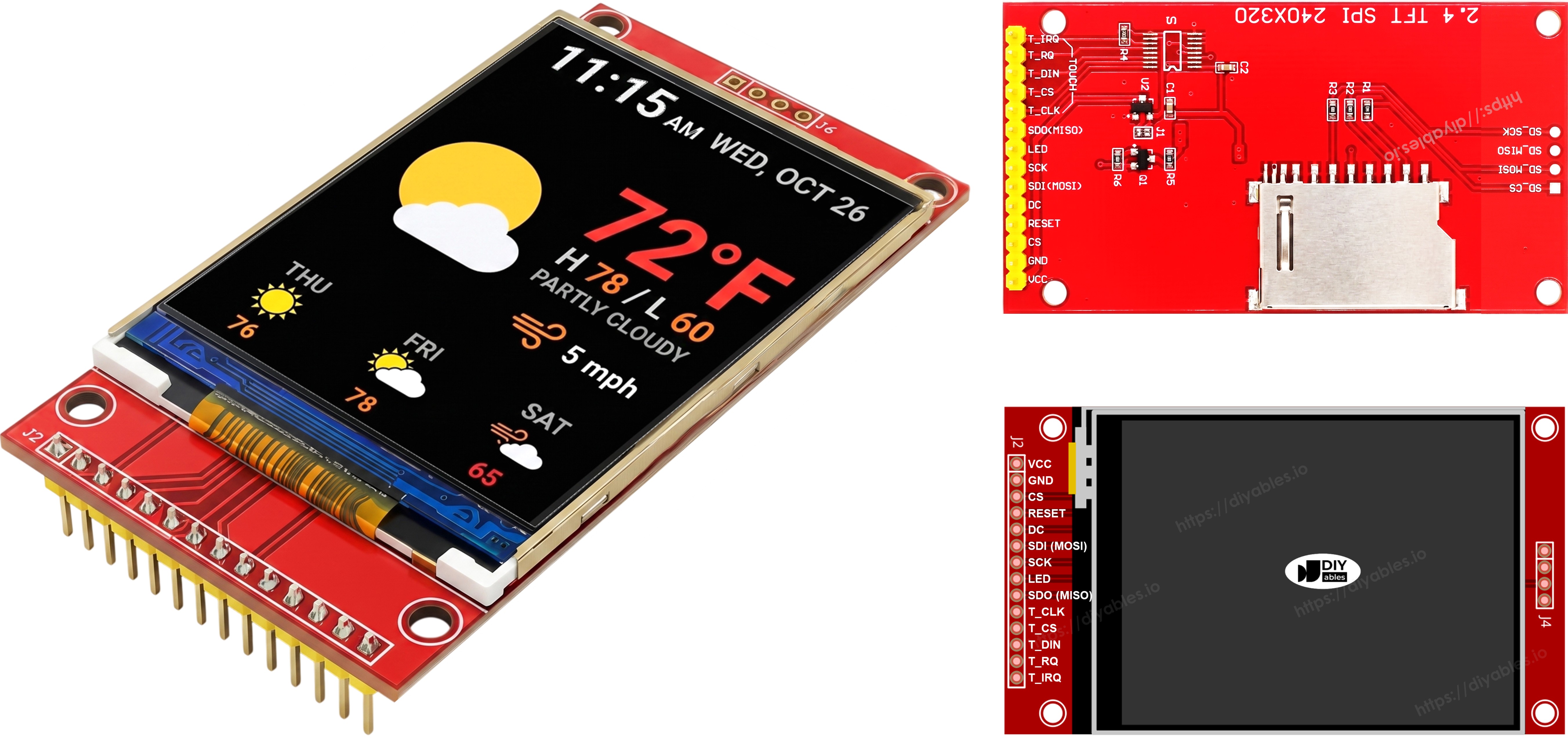
핀아웃
대부분의 SPI TFT LCD 디스플레이에는 다음 핀이 있습니다:
디스플레이 핀:
| 핀 | 기능 |
|---|---|
| VCC | 전원 공급 |
| GND | 접지 |
| CS | 칩 선택 — SPI 버스에서 디스플레이를 선택하기 위해 LOW로 당겨집니다 |
| DC / RS | 데이터/명령 선택 — 픽셀 데이터는 HIGH, 명령은 LOW |
| RST | 하드웨어 리셋 — 선택 사항; 미사용 시 3.3V에 연결 |
| MOSI / SDI / SDA | SPI 데이터 입력(MCU → 디스플레이) |
| SCK / CLK | SPI 클럭 |
| MISO / SDO | SPI 데이터 출력(디스플레이 → MCU) — 디스플레이 전용 사용 시 선택 사항 |
| LED / BL / BLK | 백라이트 전원 — 3.3V에 연결하거나 PWM 핀으로 밝기 조절 |
SD 카드 핀 (애플리케이션에서 SD 카드에 접근해야 하는 경우):
| 핀 | 기능 |
|---|---|
| SD_CS / TF_CS | SD 카드 칩 선택 |
| MOSI / SDI | MOSI — MCU에서 SD 카드로 데이터 |
| SCK / CLK | SCK — SPI 클럭 |
| MISO / SDO | MISO — SD 카드에서 MCU로 데이터 |
터치를 지원하는 TFT 디스플레이의 경우 추가 터치 핀이 있습니다:
| 핀 | 기능 |
|---|---|
| T_CS | 터치 컨트롤러 칩 선택 |
| T_CLK | SCK — SPI 클럭 |
| T_DIN | MOSI — MCU에서 터치 컨트롤러로 데이터 |
| T_DO | MISO — 터치 컨트롤러에서 MCU로 데이터 |
| T_IRQ | 터치 인터럽트 — 선택 사항; 화면이 터치될 때 신호를 보냄 |
참고: 일부 비터치 디스플레이 모듈에도 T_CS, T_CLK, T_DIN, T_DO, T_IRQ 핀이 노출되어 있습니다. 이러한 보드에서는 비기능적입니다 — 터치 컨트롤러 IC가 탑재되지 않습니다. 제조 변형을 줄이기 위해 동일한 PCB 레이아웃을 재사용하기 때문에 나타납니다.
배선도
터치 없는 버전
ESP8266 NodeMCU의 MOSI를 D7(GPIO13), SCK를 D5(GPIO14), MISO를 D6(GPIO12)에 연결합니다. CS, DC, RST는 사용 가능한 부팅 안전 GPIO 중 하나를 사용합니다 — 예제에서는 D2(GPIO4), D1(GPIO5), D0(GPIO16)를 사용합니다.
디스플레이:
| TFT 핀 | ESP8266 NodeMCU 핀 | GPIO 번호 | 설명 |
|---|---|---|---|
| VCC | 3V3 | - | 전원 공급(3.3V만) |
| GND | GND | - | 접지 |
| CS | D2 | GPIO4 | 칩 선택(부팅 안전) |
| DC / RS | D1 | GPIO5 | 데이터/명령 선택(부팅 안전) |
| RST | D0 | GPIO16 | 리셋(부팅 안전, 선택 사항) |
| MOSI / SDI | D7 | GPIO13 | 하드웨어 SPI MOSI |
| SCK | D5 | GPIO14 | 하드웨어 SPI 클럭 |
| MISO / SDO | D6 | GPIO12 | 하드웨어 SPI MISO(선택 사항) |
| LED / BL | 3V3 | - | 백라이트 전원 |
SD 카드 (SD 카드 접근이 필요한 경우):
| SD 핀 | ESP8266 NodeMCU 핀 | GPIO 번호 | 설명 |
|---|---|---|---|
| SD_CS / TF_CS | D8 | GPIO15 | SD 카드 칩 선택(아래 참고 참조) |
| MOSI / SDI | D7 | GPIO13 | 디스플레이 MOSI와 공유(D7/GPIO13) |
| SCK / CLK | D5 | GPIO14 | 디스플레이 SCK와 공유(D5/GPIO14) |
| MISO / SDO | D6 | GPIO12 | 디스플레이 MISO와 공유(D6/GPIO12) |
⚠ 부팅 핀 참고(SD_CS): GPIO15(D8)는 부팅 시 LOW여야 합니다. 이 예제에서 SD_CS에 사용됩니다. 표준 SD 모듈에는 이를 자동으로 충족하는 풀다운 저항이 있습니다. SD 모듈 추가 후 업로드가 중단되면 SD_CS 와이어를 분리하고 재시도한 후 다시 연결하세요.
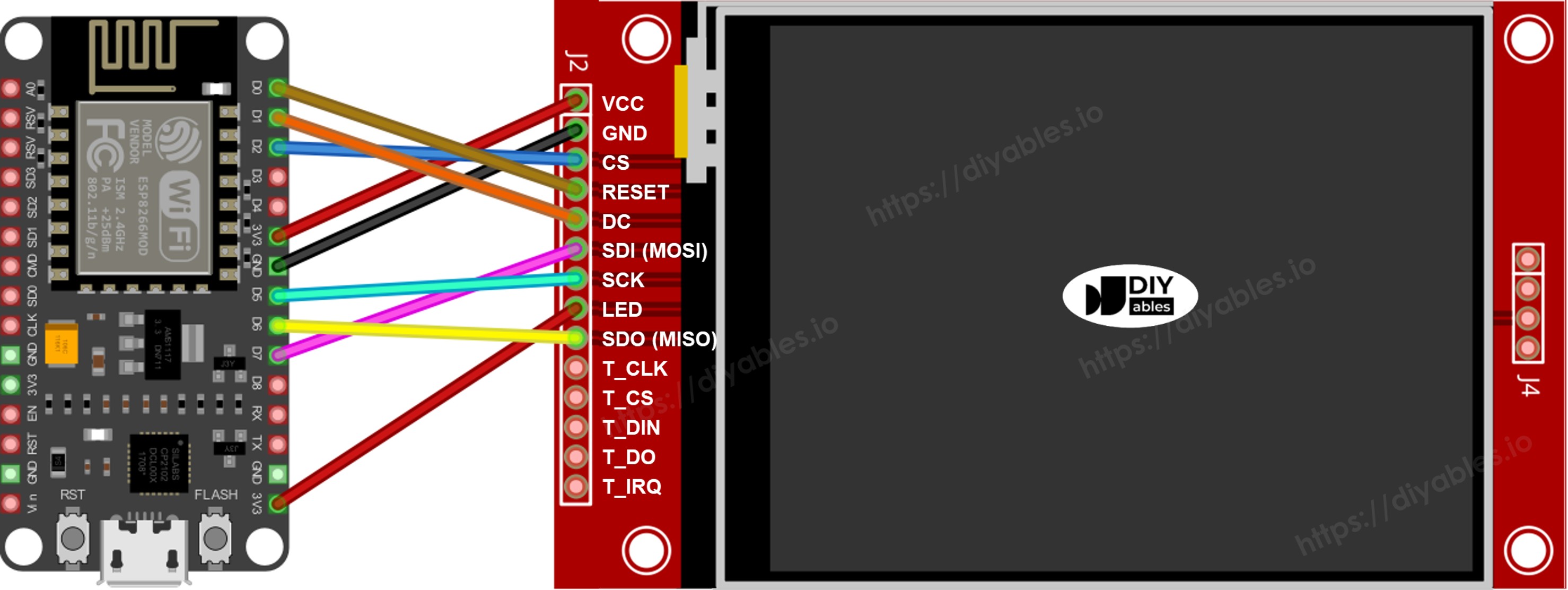
이 이미지는 Fritzing을 사용하여 만들어졌습니다. 이미지를 확대하려면 클릭하세요.
ESP8266 핀배열 및 ESP8266 전원을 켜는 방법에 대해 더 많이 보십시오.
터치 버전
XPT2046 터치 컨트롤러를 디스플레이와 D7(GPIO13), D5(GPIO14), D6(GPIO12) SPI 버스를 공유하여 ESP8266 NodeMCU에 연결합니다.
터치 컨트롤러:
| Touch 핀 | ESP8266 NodeMCU 핀 | GPIO 번호 | 설명 |
|---|---|---|---|
| T_CS | D3 | GPIO0 | 터치 칩 선택(부팅 민감) |
| T_IRQ | D4 | GPIO2 | 터치 인터럽트, 선택 사항(부팅 민감) |
| T_DIN | D7 | GPIO13 | 디스플레이 MOSI와 공유(D7/GPIO13) |
| T_CLK | D5 | GPIO14 | 디스플레이 SCK와 공유(D5/GPIO14) |
| T_DO | D6 | GPIO12 | 디스플레이 MISO와 공유(D6/GPIO12) |
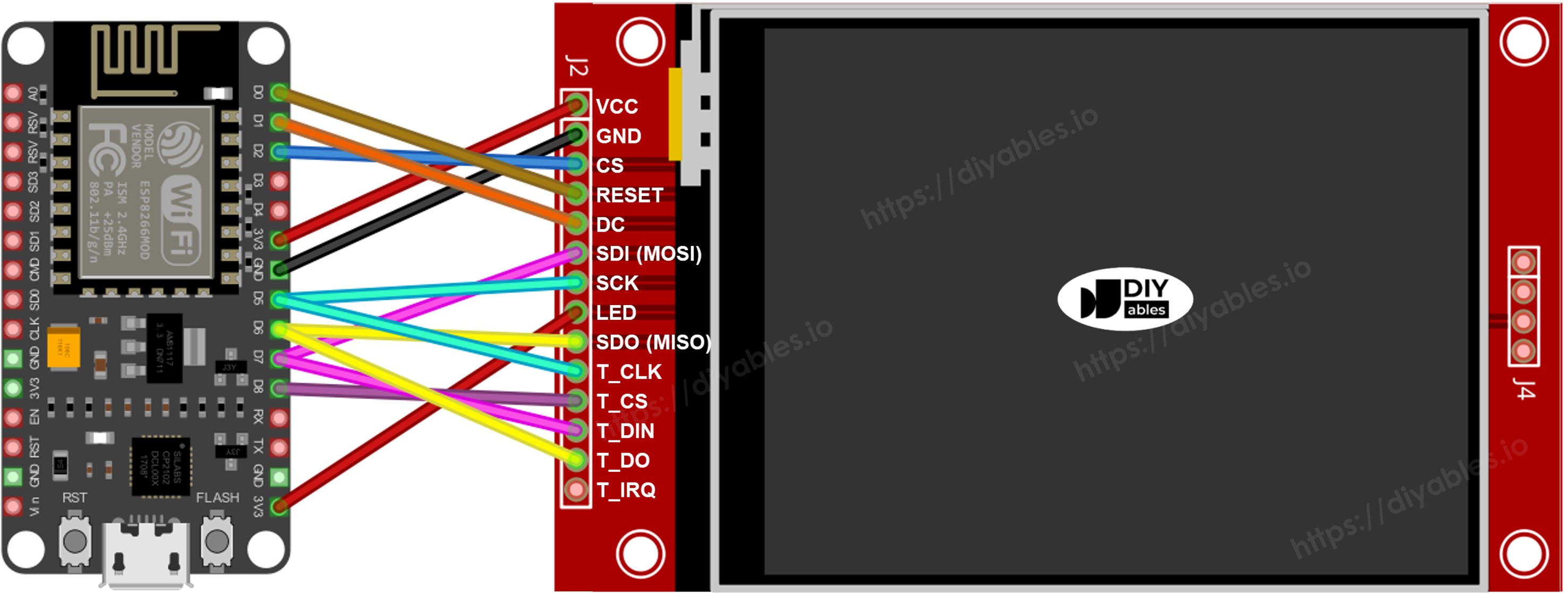
이 이미지는 Fritzing을 사용하여 만들어졌습니다. 이미지를 확대하려면 클릭하세요.
라이브러리 설치
- Micro-B USB 케이블로 NodeMCU를 컴퓨터에 연결합니다.
- Arduino IDE를 엽니다. 보드 목록에서 NodeMCU 1.0 (ESP-12E Module)을 선택하고 올바른 포트를 선택합니다.
- Libraries 패널을 엽니다.
- 검색창에 "DIYables_TFT_SPI"를 입력하고 DIYables 항목을 찾습니다.
- Install을 클릭합니다. 모든 종속성 설치를 수락합니다.
- Search for DIYables TFT SPI created by DIYables.io and click the Install button.
시작 코드
모든 ESP8266 TFT 스케치는 다음 기반에서 시작됩니다:
실습 - 도형 그리기
DrawShapes 예제는 Adafruit GFX 드로잉 API를 사용하여 원, 삼각형, 사각형, 모서리가 둥근 사각형, 선을 그립니다.
코드 실행
- 위 표에 따라 TFT 모듈을 NodeMCU에 배선합니다. 3.3V에서만 전원을 공급합니다.
- Micro-B USB 케이블을 연결합니다.
- Arduino IDE에서 보드와 포트를 선택하고, 코드를 붙여넣은 후 Upload를 누릅니다.
- 디스플레이에 반복되는 색상 도형 패턴이 표시됩니다.
드로잉 함수
| 메서드 | 그리는 내용 | 예제 |
|---|---|---|
| begin() | 디스플레이 초기화. | TFT_display.begin(); |
| setRotation(r) | 방향 설정 0-3. | TFT_display.setRotation(1); |
| fillScreen(color) | 단색으로 화면 채우기. | TFT_display.fillScreen(BLACK); |
| colorRGB(r,g,b) | R, G, B에서 16비트 색상 구성. | colorRGB(255,200,0) |
| fillCircle(x,y,r,color) | 채워진 원. | TFT_display.fillCircle(80,80,40,RED); |
| fillRect(x,y,w,h,color) | 채워진 사각형. | TFT_display.fillRect(10,10,80,50,BLUE); |
| drawFastHLine(x,y,w,color) | 수평선(빠름). | TFT_display.drawFastHLine(0,120,240,WHITE); |
실습 - 텍스트 및 숫자 표시
ShowTextAndNumber 예제는 Adafruit GFX 텍스트 엔진을 사용하여 문자열과 숫자 값을 렌더링합니다.
코드 실행
- 위와 같이 배선하고 업로드합니다.
- 디스플레이에 다양한 크기와 색상의 텍스트 줄이 표시됩니다.
드로잉 함수
| 메서드 | 그리는 내용 | 예제 |
|---|---|---|
| setTextColor(color) | 텍스트 전경색 설정. | TFT_display.setTextColor(WHITE); |
| setTextSize(size) | 텍스트 배율. 크기 1 = 6×8 px, 크기 2 = 12×16 px. | TFT_display.setTextSize(2); |
| setCursor(x, y) | 픽셀 (x, y)에 텍스트 커서 위치 지정. | TFT_display.setCursor(10, 20); |
| print(value) | 커서 위치에 문자열이나 숫자 렌더링. | TFT_display.print("NodeMCU!"); |
| println(value) | 렌더링하고 커서를 다음 줄로 이동. | TFT_display.println(42); |
실습 - 이미지 그리기
디스플레이에 비트맵 이미지를 로드해 봅니다. DrawImage 예제는 bitmap.h 내부의 PROGMEM const uint16_t 배열로 프로그램 플래시에 저장된 전체 컬러 RGB565 이미지를 렌더링합니다. ESP8266에서 PROGMEM 데이터는 SPI 플래시 메모리에 배치되며 직접 포인터 역참조 대신 플래시 읽기 명령을 통해 접근합니다. DIYables_TFT_SPI 라이브러리가 이를 투명하게 처리합니다.
컴파일 전에 bitmap.h를 스케치와 같은 폴더에 배치합니다.
코드 실행
- Bitmap.h를 스케치와 같은 폴더에 복사합니다.
- 위 배선도에 따라 TFT 모듈을 NodeMCU에 배선합니다. VCC에 3.3V를 사용합니다.
- Micro-B USB 케이블을 연결합니다.
- Arduino IDE에서 보드와 포트를 선택하고 Upload를 누릅니다.
- 디스플레이에 프로그램 플래시에서 로드된 비트맵 이미지가 표시됩니다.
동영상
비디오 제작은 시간이 많이 걸리는 작업입니다. 비디오 튜토리얼이 학습에 도움이 되었다면, YouTube 채널 을 구독하여 알려 주시기 바랍니다. 비디오에 대한 높은 수요가 있다면, 비디오를 만들기 위해 노력하겠습니다.


