아두이노 우노 R4 WiFi 블루투스 디지털 핀 예제 BLE를 통한 GPIO 핀 제어 튜토리얼
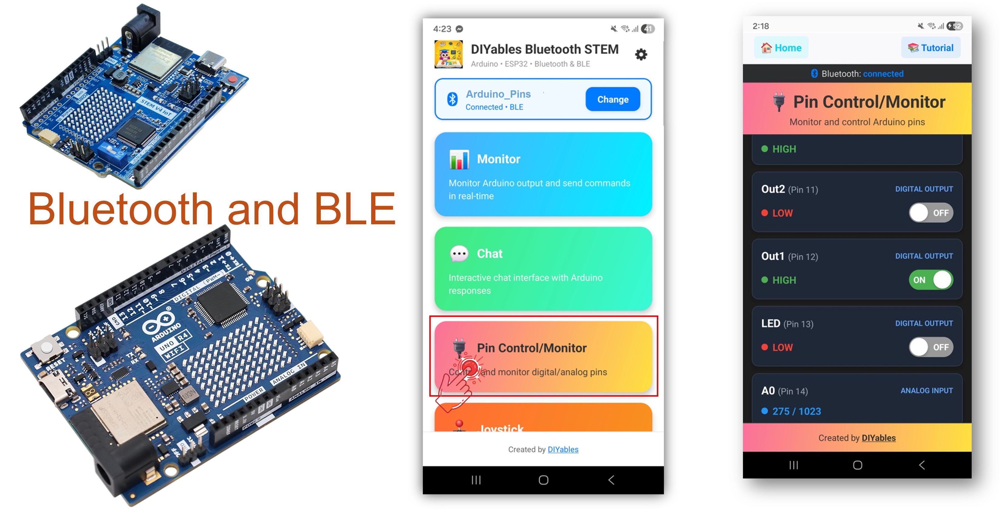
블루투스 디지털 핀 예제는 DIYables 블루투스 STEM 앱을 통해 원격 GPIO 핀 제어 및 모니터링 기능을 제공합니다. BLE(Bluetooth Low Energy) 를 사용하는 Arduino UNO R4 WiFi 전용으로 설계되어 스마트폰에서 무선으로 출력 핀을 제어하고 입력 핀을 모니터링할 수 있습니다. 릴레이 제어, 버튼 모니터링, LED 전환 및 원격 핀 접근이 필요한 모든 애플리케이션에 적합합니다.
참고: Arduino UNO R4 WiFi는 BLE(Bluetooth Low Energy)만 지원 합니다. 클래식 블루투스는 지원하지 않습니다. DIYables 블루투스 앱은 Android에서 BLE와 클래식 블루투스를 모두 지원하고, iOS에서는 BLE를 지원합니다. 이 보드는 BLE를 사용하므로 앱은 Android와 iOS 모두 에서 작동합니다.
출력 제어 : 원격으로 디지털 핀을 HIGH /LOW로 설정
입력 모니터링 : 디지털 및 아날로그 핀 상태 읽기
핀 이름 지정 : 각 핀에 친숙한 이름 할당(예: "LED", "Relay")
실시간 업데이트 : 앱에 핀 상태 변화 푸시
최대 16개 핀 : 여러 핀 동시 제어
Android 및 iOS에서 작동 : BLE는 두 플랫폼 모두에서 지원
페어링 불필요 : BLE는 수동 페어링 없이 자동 연결
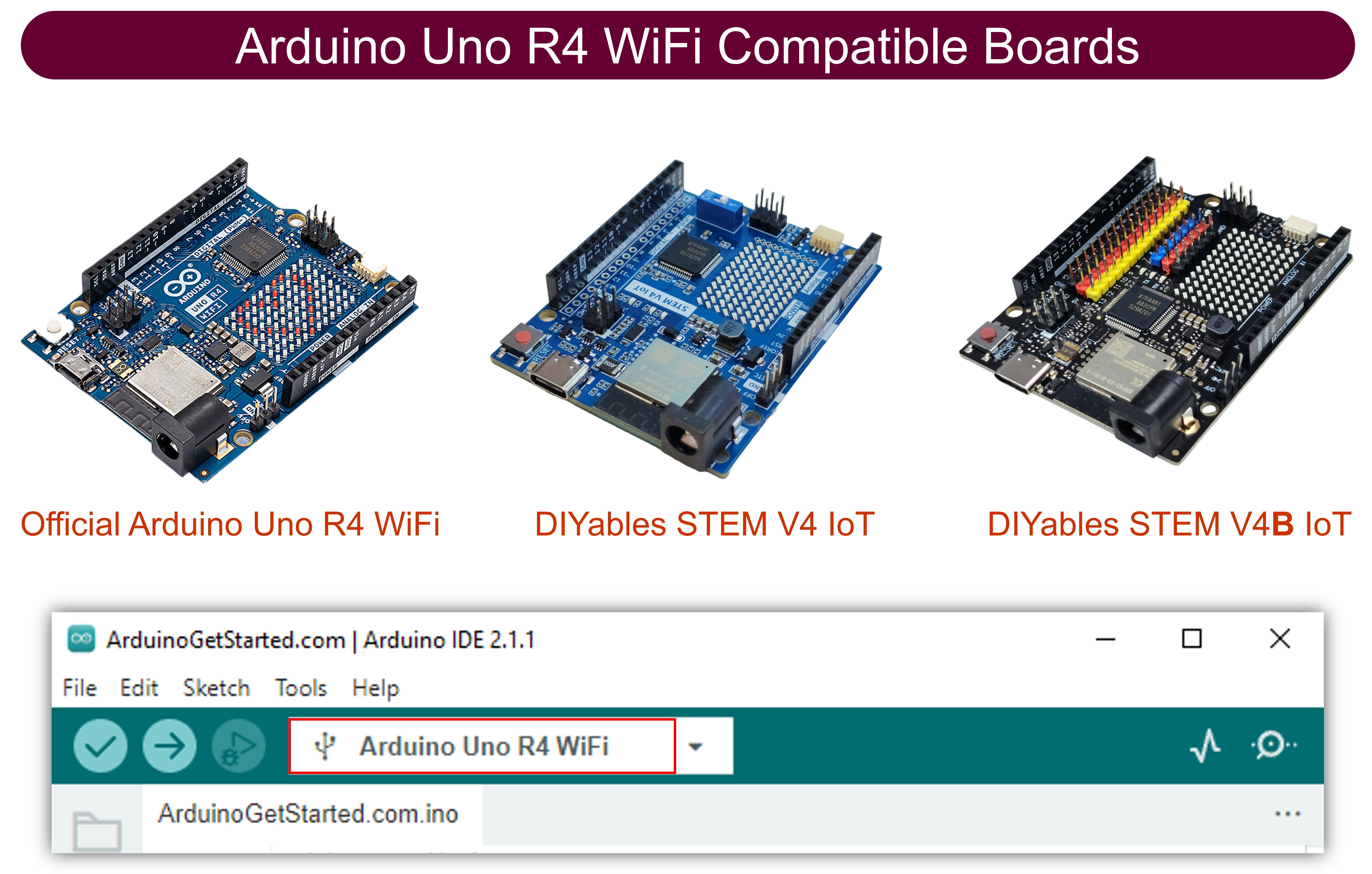
1 × 아두이노 우노 R4 와이파이 쿠팡 | 아마존 1 × (또는) DIYables STEM V4 IoT 쿠팡 | 아마존 1 × USB 케이블 타입-A to 타입-C (USB-A PC용) 쿠팡 | 아마존 1 × USB 케이블 타입-C to 타입-C (USB-C PC용) 아마존 1 × 브레드보드 쿠팡 | 아마존 1 × 점퍼케이블 쿠팡 | 아마존 1 × (추천 ) 아두이노 우노 R4용 스크루 터미널 블록 쉴드 쿠팡 | 아마존 1 × (추천 ) Sensors/Servo Expansion Shield for Arduino UNO R4 쿠팡 | 아마존 1 × (추천 ) 아두이노 우노 R4용 브레드보드 쉴드 쿠팡 | 아마존 1 × (추천 ) 아두이노 우노 R4용 케이스 쿠팡 | 아마존 1 × (추천 ) 아두이노 우노 R4용 전원 분배기 쿠팡 | 아마존 1 × (추천 ) 아두이노 우노용 프로토타이핑 베이스 플레이트 & 브레드보드 키트 아마존
공개: 이 포스팅 에 제공된 일부 링크는 아마존 제휴 링크입니다. 이 포스팅은 쿠팡 파트너스 활동의 일환으로, 이에 따른 일정액의 수수료를 제공받습니다.
다음 단계를 순서대로 따라하세요:
USB 케이블을 사용하여 Arduino UNO R4 WiFi 보드를 컴퓨터에 연결합니다.
컴퓨터에서 Arduino IDE를 실행합니다.
Arduino UNO R4 WiFi 보드와 적절한 COM 포트를 선택합니다.
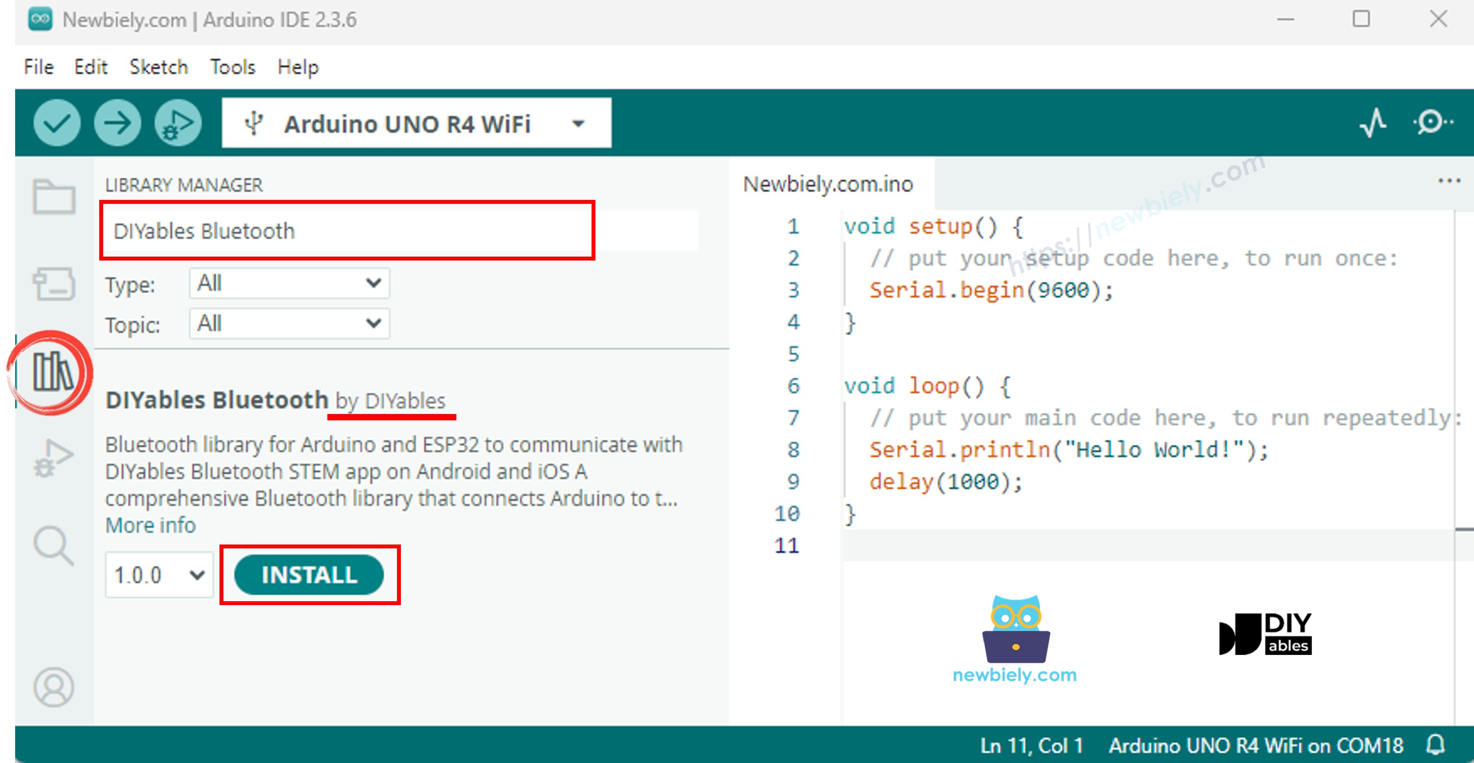
Arduino IDE 왼쪽 바에서 Libraries 아이콘으로 이동합니다.
"DIYables Bluetooth" 를 검색한 다음 DIYables의 DIYables Bluetooth 라이브러리를 찾습니다.
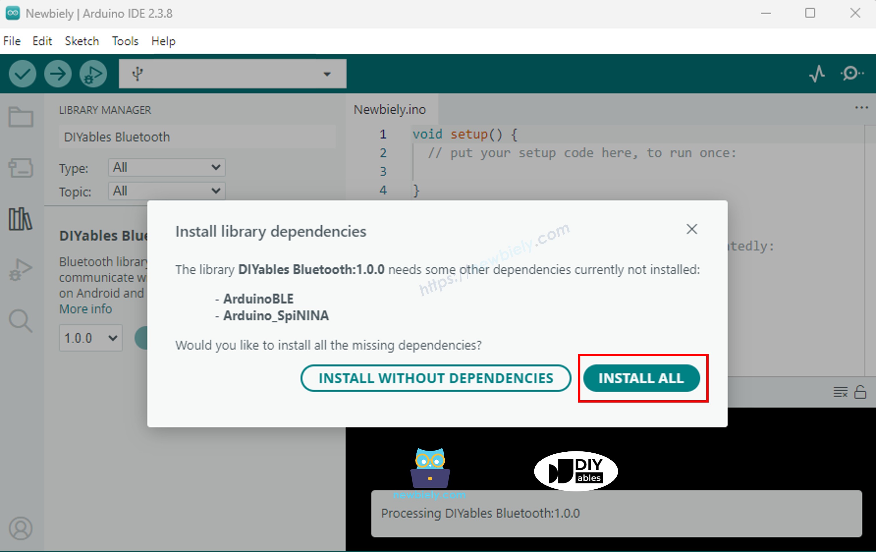
Install 버튼을 클릭하여 라이브러리를 설치합니다.
#include <DIYables_BluetoothServer .h>
#include <DIYables_BluetoothPinControl .h>
#include <platforms/DIYables_ArduinoBLE.h>
const char* DEVICE_NAME = "Arduino_Pins" ;const char* SERVICE_UUID = "19B10000-E8F2-537E-4F6C-D104768A1214" ;const char* TX_UUID = "19B10001-E8F2-537E-4F6C-D104768A1214" ;const char* RX_UUID = "19B10002-E8F2-537E-4F6C-D104768A1214" ;DIYables_ArduinoBLE bluetooth(DEVICE_NAME, SERVICE_UUID, TX_UUID, RX_UUID);DIYables_BluetoothServer bluetoothServer(bluetooth);DIYables_BluetoothPinControl bluetoothPins;const int LED_PIN = 13;const int OUTPUT_PIN_1 = 12;const int OUTPUT_PIN_2 = 11;const int INPUT_PIN_1 = 7;const int INPUT_PIN_2 = 6;const int ANALOG_PIN_1 = A0;const int ANALOG_PIN_2 = A1;void setup () { Serial .begin (9600);
while (!Serial );
Serial .println ("DIYables Bluetooth - Pin Control/Monitor Example" );
pinMode (LED_PIN, OUTPUT );
pinMode (OUTPUT_PIN_1, OUTPUT );
pinMode (OUTPUT_PIN_2, OUTPUT );
pinMode (INPUT_PIN_1, INPUT_PULLUP );
pinMode (INPUT_PIN_2, INPUT_PULLUP );
bluetoothServer.begin ();
bluetoothServer.addApp (&bluetoothPins);
bluetoothPins.enablePin (LED_PIN, BT_PIN_OUTPUT , "LED" );
bluetoothPins.enablePin (OUTPUT_PIN_1, BT_PIN_OUTPUT , "Out1" );
bluetoothPins.enablePin (OUTPUT_PIN_2, BT_PIN_OUTPUT , "Out2" );
bluetoothPins.enablePin (INPUT_PIN_1, BT_PIN_INPUT , "Btn1" );
bluetoothPins.enablePin (INPUT_PIN_2, BT_PIN_INPUT , "Btn2" );
bluetoothPins.enablePin (ANALOG_PIN_1, BT_PIN_INPUT , "A0" );
bluetoothPins.enablePin (ANALOG_PIN_2, BT_PIN_INPUT , "A1" );
bluetoothServer.setOnConnected ([]() {
Serial .println ("Bluetooth connected!" );
});
bluetoothServer.setOnDisconnected ([]() {
Serial .println ("Bluetooth disconnected!" );
});
bluetoothPins.onPinWrite ([](int pin, int state) {
digitalWrite (pin, state);
Serial .print ("Pin " );
Serial .print (pin);
Serial .print (" set to " );
Serial .println (state ? "HIGH" : "LOW" );
});
bluetoothPins.onPinRead ([](int pin) -> int {
int state;
if (pin == ANALOG_PIN_1 || pin == ANALOG_PIN_2) {
state = analogRead (pin);
Serial .print ("Analog pin " );
Serial .print (pin);
Serial .print (" read: " );
Serial .println (state);
} else {
state = digitalRead (pin);
Serial .print ("Digital pin " );
Serial .print (pin);
Serial .print (" read: " );
Serial .println (state ? "HIGH" : "LOW" );
}
return state;
});
bluetoothPins.onPinModeChange ([](int pin, int mode) {
pinMode (pin, mode == BT_PIN_OUTPUT ? OUTPUT : INPUT_PULLUP );
Serial .print ("Pin " );
Serial .print (pin);
Serial .print (" mode changed to " );
Serial .println (mode == BT_PIN_OUTPUT ? "OUTPUT" : "INPUT" );
});
Serial .println ("Waiting for Bluetooth connection..." );
Serial .print ("Enabled pins: " );
Serial .println (bluetoothPins.getEnabledPinCount ());
}
void loop () {
bluetoothServer.loop ();
static unsigned long lastInputCheck = 0;
static int lastInputState1 = HIGH ;
static int lastInputState2 = HIGH ;
static int lastAnalogState1 = 0;
static int lastAnalogState2 = 0;
if (millis () - lastInputCheck >= 100) {
lastInputCheck = millis ();
int currentState1 = digitalRead (INPUT_PIN_1);
if (currentState1 != lastInputState1) {
lastInputState1 = currentState1;
bluetoothPins.updatePinState (INPUT_PIN_1, currentState1);
Serial .print ("Input pin " );
Serial .print (INPUT_PIN_1);
Serial .print (" changed to " );
Serial .println (currentState1 ? "HIGH" : "LOW" );
}
int currentState2 = digitalRead (INPUT_PIN_2);
if (currentState2 != lastInputState2) {
lastInputState2 = currentState2;
bluetoothPins.updatePinState (INPUT_PIN_2, currentState2);
Serial .print ("Input pin " );
Serial .print (INPUT_PIN_2);
Serial .print (" changed to " );
Serial .println (currentState2 ? "HIGH" : "LOW" );
}
int currentAnalog1 = analogRead (ANALOG_PIN_1);
if (abs (currentAnalog1 - lastAnalogState1) > 10) {
lastAnalogState1 = currentAnalog1;
bluetoothPins.updatePinState (ANALOG_PIN_1, currentAnalog1);
Serial .print ("Analog pin " );
Serial .print (ANALOG_PIN_1);
Serial .print (" changed to " );
Serial .println (currentAnalog1);
}
int currentAnalog2 = analogRead (ANALOG_PIN_2);
if (abs (currentAnalog2 - lastAnalogState2) > 10) {
lastAnalogState2 = currentAnalog2;
bluetoothPins.updatePinState (ANALOG_PIN_2, currentAnalog2);
Serial .print ("Analog pin " );
Serial .print (ANALOG_PIN_2);
Serial .print (" changed to " );
Serial .println (currentAnalog2);
}
}
delay (10);
}
∞
Newbiely | Arduino IDE 2.3.8
8
Serial .println ("Hello World!" );
Message (Enter to send message to 'Arduino Uno R4 WiFi' on 'COM15')
DIYables Bluetooth - Pin Control/Monitor Example
Waiting for Bluetooth connection...
Enabled pins: 7
Ln 11, Col 1
Arduino Uno R4 WiFi on COM15
2
참고: DIYables 블루투스 앱은 Android에서 BLE와 클래식 블루투스를 모두 지원하고, iOS에서는 BLE를 지원합니다. Arduino UNO R4 WiFi는 BLE를 사용하므로 앱은 Android와 iOS 모두 에서 작동합니다. BLE에는 수동 페어링이 필요 없으며 스캔하고 연결하기만 하면 됩니다.
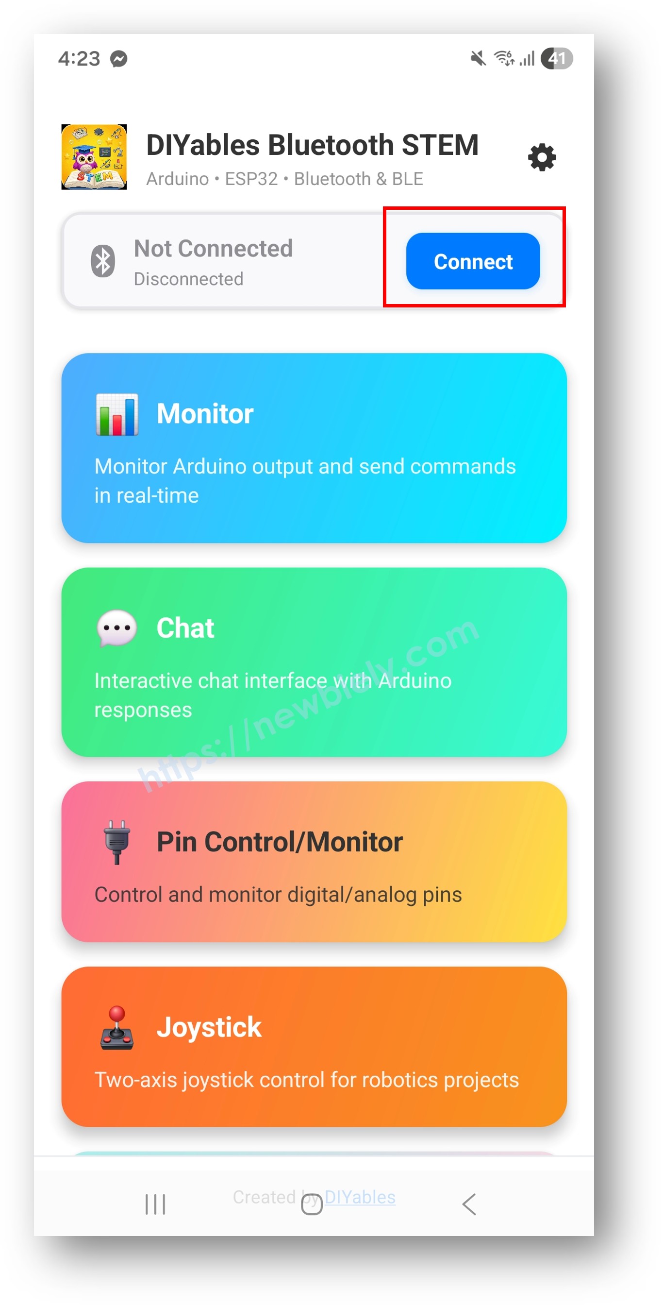
DIYables 블루투스 앱을 엽니다.
처음 앱을 열면 권한을 요청합니다. 다음을 허용해 주세요:
휴대폰에서 블루투스가 켜져 있는지 확인합니다.
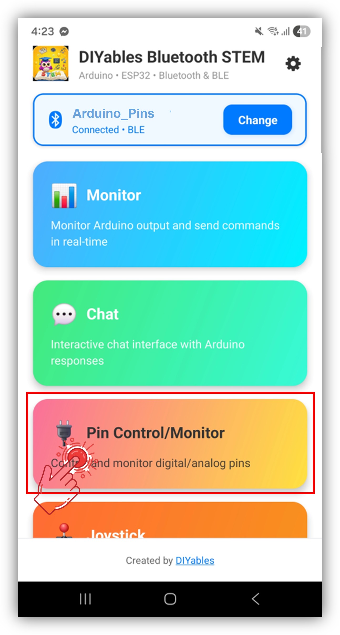
홈 화면에서 Connect 버튼을 탭합니다. 앱이 BLE 기기를 스캔합니다.
참고: 홈 화면의 설정 아이콘을 탭하면 앱을 표시하거나 숨길 수 있습니다. 자세한 내용은 DIYables 블루투스 앱 사용 설명서 를 참조하세요.
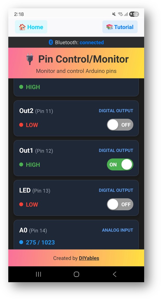
활성화된 핀 목록과 이름, 현재 상태가 표시됩니다.
출력 핀을 탭하여 HIGH /LOW를 전환하고, 입력 핀 값이 업데이트되는 것을 확인합니다.
이제 Arduino IDE의 시리얼 모니터를 다시 확인하세요. 다음과 같이 표시됩니다:
∞
Newbiely | Arduino IDE 2.3.8
8
Serial .println ("Hello World!" );
Message (Enter to send message to 'Arduino Uno R4 WiFi' on 'COM15')
Bluetooth connected!
Pin 13 set to HIGH
Pin 13 set to LOW
Digital pin 7 read: HIGH
Ln 11, Col 1
Arduino Uno R4 WiFi on COM15
2
bluetoothPins.enablePin (13, BT_PIN_OUTPUT , "LED" );
bluetoothPins.enablePin (12, BT_PIN_OUTPUT , "Relay" );
bluetoothPins.enablePin (7, BT_PIN_INPUT , "Button" );
bluetoothPins.enablePin (A0, BT_PIN_INPUT , "Sensor" );
int count = bluetoothPins.getEnabledPinCount ();
bluetoothPins.onPinWrite ([](int pin, int state) {
digitalWrite (pin, state);
Serial .print ("Pin " );
Serial .print (pin);
Serial .println (state ? " ? HIGH" : " ? LOW" );
});
bluetoothPins.onPinRead ([](int pin) -> int {
if (pin >= A0) {
return analogRead (pin);
}
return digitalRead (pin);
});
bluetoothPins.onPinModeChange ([](int pin, int mode) {
pinMode (pin, mode == BT_PIN_OUTPUT ? OUTPUT : INPUT_PULLUP );
});
bluetoothPins.updatePinState (7, digitalRead (7));
bluetoothPins.updatePinState (A0, analogRead (A0));
const int RELAY_PIN = 12;const int BUTTON_PIN = 7;void setup () { pinMode (RELAY_PIN, OUTPUT );
pinMode (BUTTON_PIN, INPUT_PULLUP );
bluetoothPins.enablePin (RELAY_PIN, BT_PIN_OUTPUT , "Relay" );
bluetoothPins.enablePin (BUTTON_PIN, BT_PIN_INPUT , "Button" );
bluetoothPins.onPinWrite ([](int pin, int state) {
digitalWrite (pin, state);
});
}
void loop () { bluetoothServer.loop ();
static int lastState = HIGH ;
int state = digitalRead (BUTTON_PIN);
if (state != lastState) {
lastState = state;
bluetoothPins.updatePinState (BUTTON_PIN, state);
}
delay (10);
}
const int LED_PINS[] = {8, 9, 10, 11, 12, 13};const char* LED_NAMES[] = {"Red" , "Green" , "Blue" , "Yellow" , "White" , "Built-in" };const int NUM_LEDS = 6;void setup () { for (int i = 0; i < NUM_LEDS; i++) {
pinMode (LED_PINS[i], OUTPUT );
bluetoothPins.enablePin (LED_PINS[i], BT_PIN_OUTPUT , LED_NAMES[i]);
}
bluetoothPins.onPinWrite ([](int pin, int state) {
digitalWrite (pin, state);
});
}
1. 앱에서 기기를 찾을 수 없음
Arduino UNO R4 WiFi가 전원이 켜져 있고 스케치가 업로드되어 있는지 확인하세요.
휴대폰의 블루투스가 활성화되어 있는지 확인하세요.
Android 11 이하에서는 위치 서비스도 활성화하세요.
2. 핀 전환이 작동하지 않음
3. 입력 핀이 업데이트되지 않음
4. 아날로그 값이 표시되지 않음
5. 연결이 자주 끊김
6. 업로드 실패 또는 보드를 인식하지 못함
다중 릴레이 제어판
버튼 및 스위치 모니터
LED 조명 컨트롤러
홈 자동화 스위치 패널
센서 입력 대시보드
블루투스 디지털 핀 예제를 마스터한 후 다음을 시도해 보세요:
블루투스 슬라이더 - 아날로그 값 제어용
블루투스 모니터 - 텍스트 기반 상태 피드백용
블루투스 테이블 - 구조화된 핀 상태 표시용
다중 블루투스 앱 - 핀 제어와 다른 앱 결합
추가 도움이 필요하면:
API 레퍼런스 문서를 확인하세요.
Arduino 커뮤니티 포럼