공개: 이 포스팅 에 제공된 일부 링크는 아마존 제휴 링크입니다. 이 포스팅은 쿠팡 파트너스 활동의 일환으로, 이에 따른 일정액의 수수료를 제공받습니다.
TCS3200D/TCS230 컬러 센서에 대하여
TCS3200D/TCS230은 8×8 배열의 포토다이오드를 사용하는 색상 인식 센서 모듈입니다. 16개의 포토다이오드는 빨간색 필터, 16개는 녹색 필터, 16개는 파란색 필터, 16개는 투명(필터 없음)으로 되어 있습니다. 모듈은 빛의 강도를 구형파 주파수 신호로 변환합니다. 색상 필터를 전환하고 출력 주파수(또는 펄스 폭)를 측정함으로써 객체의 RGB 값을 추정할 수 있습니다.
많은 모듈에는 대상을 조명하기 위한 흰색 LED가 포함되어 있습니다. 이로 인해 판독값이 더 일관되고 저조도에서도 센서가 색상을 안정적으로 감지할 수 있습니다.
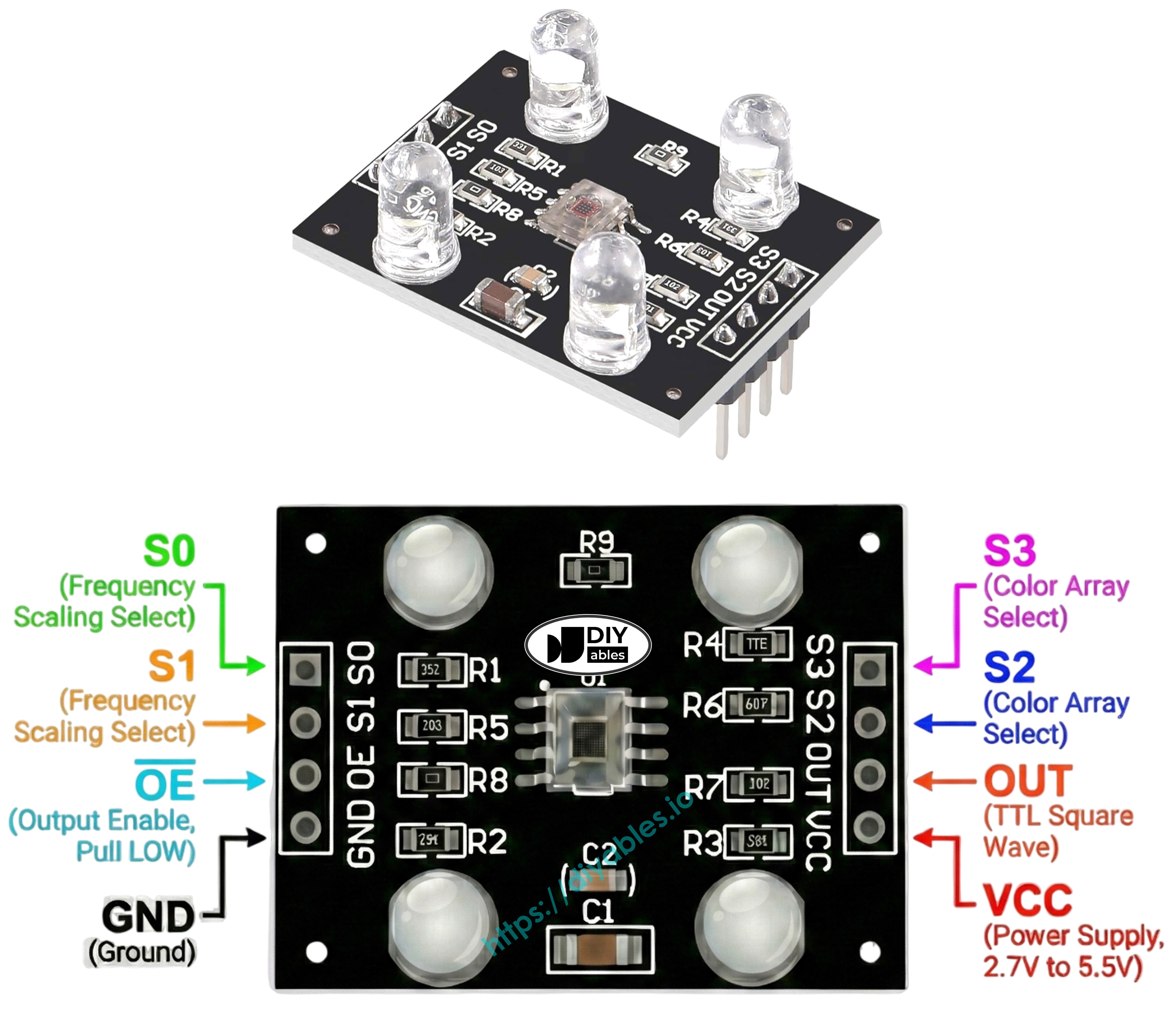
핀아웃
TCS3200D/TCS230 컬러 센서 모듈에는 일반적으로 다음 핀이 있습니다:
VCC 핀: 이 핀을 VCC(5V)에 연결합니다.
GND 핀: 이 핀을 GND(0V)에 연결합니다.
S0, S1 핀: 출력 주파수 스케일링 선택.
S2, S3 핀: 색상 필터 선택.
OUT 핀: 구형파 주파수 출력.
OE 핀: 출력 활성화(액티브 LOW). 대부분의 모듈은 이 핀을 GND에 내부적으로 연결되어 있으므로 배선할 필요가 없습니다. 그렇지 않은 경우 GND에 연결합니다.
작동 원리
센서는 두 가지를 알아야 합니다: 어떤 색상 채널을 측정할지, 출력 신호를 얼마나 강하게 할지. 두 쌍의 제어 핀이 이를 처리합니다:
S0와 S1은 출력 주파수 스케일링을 제어합니다:
S0 = LOW, S1 = LOW: 전원 끄기
S0 = LOW, S1 = HIGH: 2% 스케일링
S0 = HIGH, S1 = LOW: 20% 스케일링
S0 = HIGH, S1 = HIGH: 100% 스케일링
S2와 S3은 색상 필터를 선택합니다:
S2 = LOW, S3 = LOW: 빨간색 필터
S2 = LOW, S3 = HIGH: 파란색 필터
S2 = HIGH, S3 = LOW: 투명(필터 없음)
S2 = HIGH, S3 = HIGH: 녹색 필터
OUT 핀은 구형파를 출력합니다(일반적으로 2Hz~500kHz). 주파수는 선택된 색상의 강도에 비례하고, 펄스 폭은 반비례합니다. pulseIn()을 사용하여 펄스 폭을 측정하고 보정 후 RGB 값으로 변환할 수 있습니다.
안정적인 판독값을 위한 팁
센서를 객체에서 1~3cm 거리에 놓고 각도를 일정하게 유지합니다.
내장된 흰색 LED를 사용하여 안정적인 조명을 제공합니다.
더 정확한 결과를 위해 주변 빛의 변화로부터 센서를 차폐합니다.
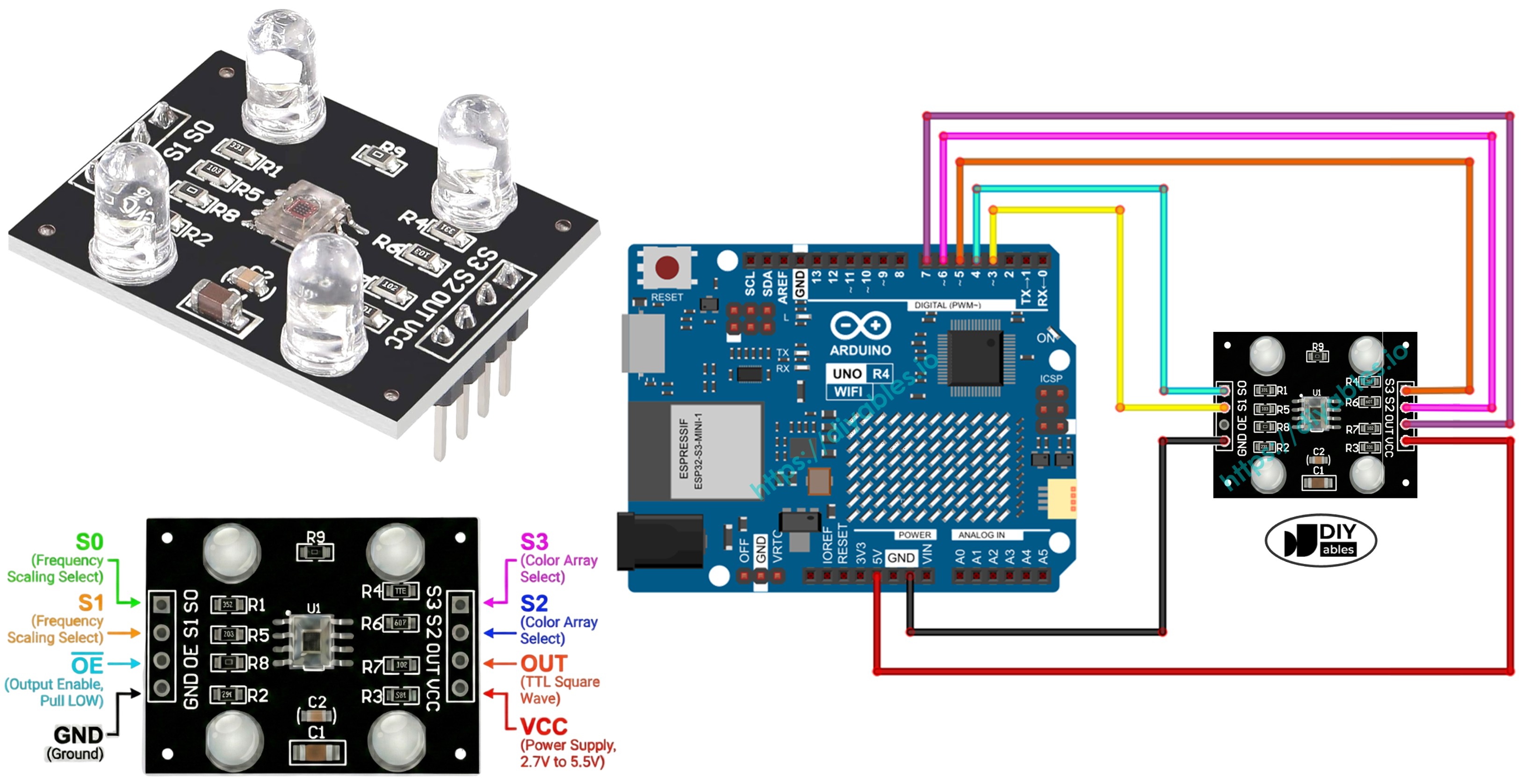
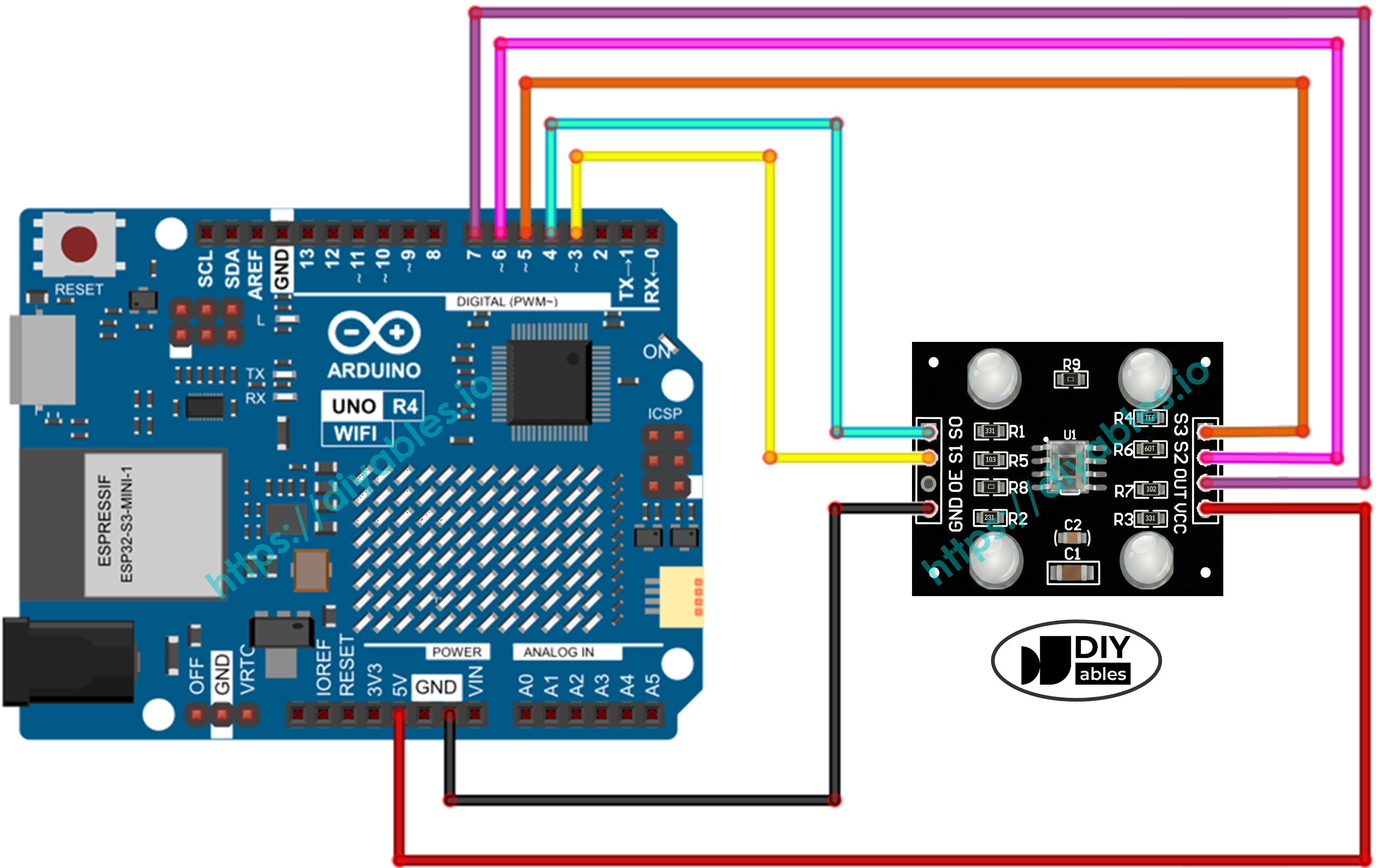
배선도
이 이미지는 TCS3200 컬러 센서를 Arduino UNO R4에 연결하는 방법을 보여줍니다:
Arduino Uno R4와 기타 부품에 전원을 공급하는 가장 효과적인 방법을 확인하시려면, 아래 링크를 참조하세요: 아두이노 우노 R4 전원 공급 방법.
Arduino UNO R4 코드 - 보정(펄스 폭)
보정은 센서의 원시 판독값이 환경의 영향을 받기 때문에 필요합니다. LED 밝기, 거리, 표면 반사율, 주변 빛과 같은 요소가 측정값을 변경합니다. 이러한 효과를 "노이즈"로 생각할 수 있습니다. 첫 번째 보정 단계는 해당 노이즈 범위(각 색상의 최솟값과 최댓값)를 측정하여 그 영향을 빼고 판독값을 설정에 맞는 올바른 0~255 RGB 값으로 매핑하는 데 도움이 됩니다.
/* * 이 아두이노 우노 R4 코드는 newbiely.kr 에서 개발되었습니다 * 이 아두이노 우노 R4 코드는 어떠한 제한 없이 공개 사용을 위해 제공됩니다. * 상세한 지침 및 연결도에 대해서는 다음을 방문하세요: * https://newbiely.kr/tutorials/arduino-uno-r4/arduino-uno-r4-tcs3200d-tcs230-color-sensor */// Define color sensor pins#define S0 4#define S1 3#define S2 6#define S3 5#define sensorOut 7// Variables for Color Pulse Width Measurementsint redPW = 0;int greenPW = 0;int bluePW = 0;// Variables to track min and max pulse widths for calibrationint redMin = 10000, redMax = 0;int greenMin = 10000, greenMax = 0;int blueMin = 10000, blueMax = 0;voidsetup() {// Set S0 - S3 as outputspinMode(S0, OUTPUT);pinMode(S1, OUTPUT);pinMode(S2, OUTPUT);pinMode(S3, OUTPUT);// Set Pulse Width scaling to 20%digitalWrite(S0, HIGH);digitalWrite(S1, LOW);// Set Sensor output as inputpinMode(sensorOut, INPUT);// Setup Serial MonitorSerial.begin(9600);Serial.println("=== TCS3200 Calibration ===");Serial.println("Point the sensor at different objects (white, black, colors).");Serial.println("Min and Max values are tracked automatically.");Serial.println("When values look stable, note them down for the next code.");Serial.println("------------------------------------------");}voidloop() {// Read Red Pulse Width redPW = getRedPW();// Delay to stabilize sensordelay(200);// Read Green Pulse Width greenPW = getGreenPW();// Delay to stabilize sensordelay(200);// Read Blue Pulse Width bluePW = getBluePW();// Delay to stabilize sensordelay(200);// Update min and max valuesif (redPW < redMin) redMin = redPW;if (redPW > redMax) redMax = redPW;if (greenPW < greenMin) greenMin = greenPW;if (greenPW > greenMax) greenMax = greenPW;if (bluePW < blueMin) blueMin = bluePW;if (bluePW > blueMax) blueMax = bluePW;// Print current readingsSerial.print("Red PW = ");Serial.print(redPW);Serial.print(" - Green PW = ");Serial.print(greenPW);Serial.print(" - Blue PW = ");Serial.println(bluePW);// Print current min/maxSerial.print(" Min -> R:");Serial.print(redMin);Serial.print(" G:");Serial.print(greenMin);Serial.print(" B:");Serial.println(blueMin);Serial.print(" Max -> R:");Serial.print(redMax);Serial.print(" G:");Serial.print(greenMax);Serial.print(" B:");Serial.println(blueMax);Serial.println("------------------------------------------");}// Function to read Red Pulse Widthsint getRedPW() {// Set sensor to read Red onlydigitalWrite(S2, LOW);digitalWrite(S3, LOW);// Define integer to represent Pulse Widthint PW;// Read the output Pulse Width PW = pulseIn(sensorOut, LOW);// Return the valuereturn PW;}// Function to read Green Pulse Widthsint getGreenPW() {// Set sensor to read Green onlydigitalWrite(S2, HIGH);digitalWrite(S3, HIGH);// Define integer to represent Pulse Widthint PW;// Read the output Pulse Width PW = pulseIn(sensorOut, LOW);// Return the valuereturn PW;}// Function to read Blue Pulse Widthsint getBluePW() {// Set sensor to read Blue onlydigitalWrite(S2, LOW);digitalWrite(S3, HIGH);// Define integer to represent Pulse Widthint PW;// Read the output Pulse Width PW = pulseIn(sensorOut, LOW);// Return the valuereturn PW;}
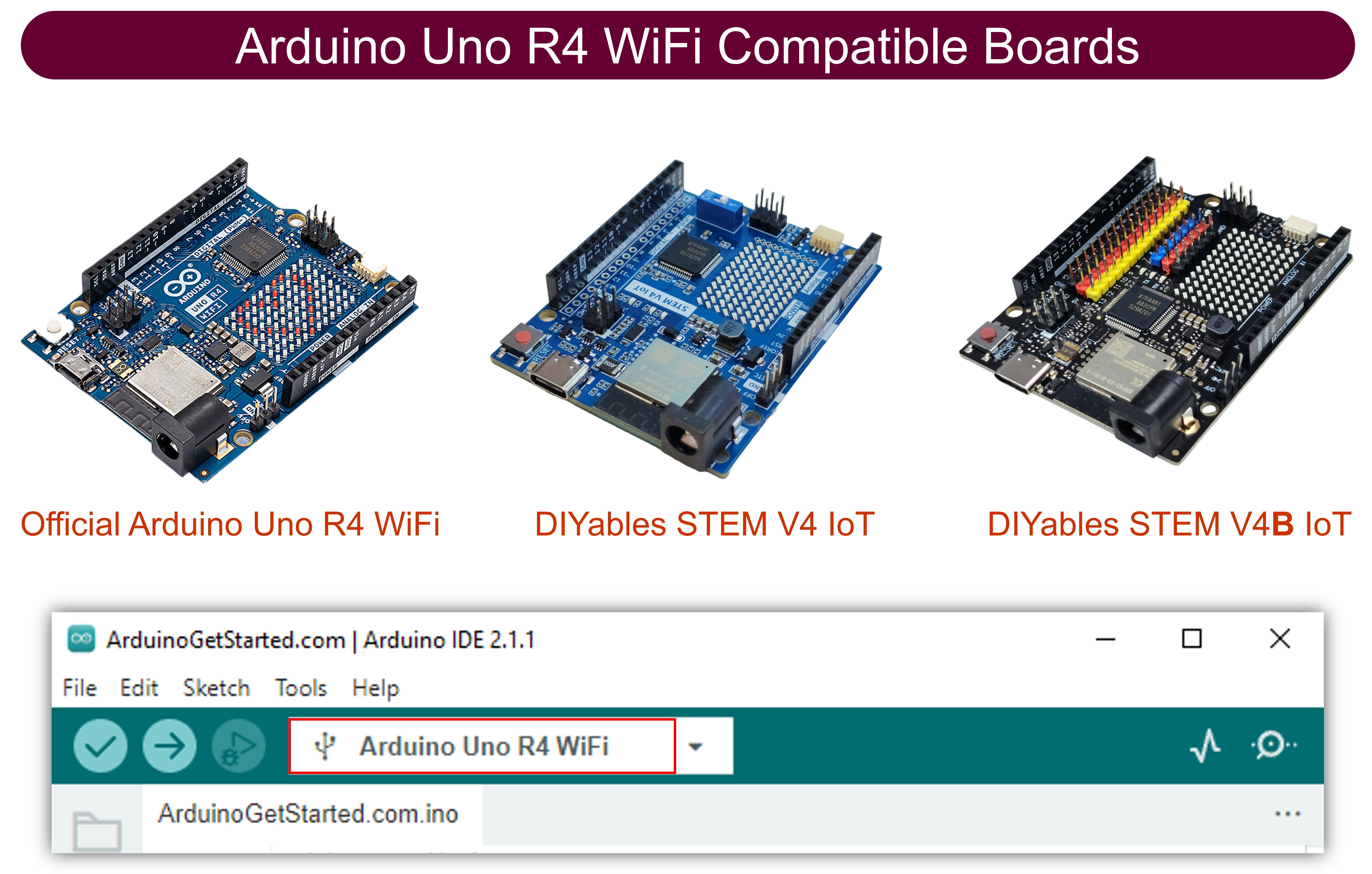
적절한 Arduino Uno R4 보드(예: Arduino Uno R4 WiFi)와 COM 포트를 선택합니다.
위의 코드를 복사하여 Arduino IDE에서 엽니다.
Arduino IDE의 Upload 버튼을 클릭하여 코드를 Arduino UNO R4에 업로드합니다.
시리얼 모니터를 엽니다. 최솟값과 최댓값과 함께 연속적인 판독값이 표시됩니다.
다양한 객체 위로 센서를 이동합니다: 흰색 객체(예: 종이), 검은색 객체, 그리고 선택적으로 색상 있는 객체.
센서가 극값을 추적하면서 Min과 Max 행이 자동으로 업데이트되는 것을 확인합니다.
Min과 Max 값이 변경을 멈추면(보통 10~20초 후), 그것이 보정 값입니다 - 기록해 두세요.
Newbiely | Arduino IDE 2.3.8
──
☐
✕
File
Edit
Sketch
Tools
Help
Arduino Uno R4 WiFi
Newbiely.ino
···
8Serial.println("Hello World!");
Output
Serial Monitor
Message (Enter to send message to 'Arduino Uno R4 WiFi' on 'COM15')
New Line
9600 baud
=== TCS3200 Calibration ===
Point the sensor at different objects (white, black, colors).
Min and Max values are tracked automatically.
When values look stable, note them down for the next code.
------------------------------------------
Red PW = 42 - Green PW = 55 - Blue PW = 60
Min -> R:42 G:55 B:60
Max -> R:42 G:55 B:60
------------------------------------------
Red PW = 210 - Green PW = 185 - Blue PW = 172
Min -> R:42 G:55 B:60
Max -> R:210 G:185 B:172
------------------------------------------
Red PW = 44 - Green PW = 57 - Blue PW = 61
Min -> R:42 G:55 B:60
Max -> R:210 G:185 B:172
------------------------------------------
Ln 11, Col 1
Arduino Uno R4 WiFi on COM15
2
예를 들어 위의 출력에서 보정 값은 다음과 같습니다:
RedMin = 42, redMax = 210
GreenMin = 55, greenMax = 185
BlueMin = 60, blueMax = 172
Arduino UNO R4 코드 - RGB 값 읽기
/* * 이 아두이노 우노 R4 코드는 newbiely.kr 에서 개발되었습니다 * 이 아두이노 우노 R4 코드는 어떠한 제한 없이 공개 사용을 위해 제공됩니다. * 상세한 지침 및 연결도에 대해서는 다음을 방문하세요: * https://newbiely.kr/tutorials/arduino-uno-r4/arduino-uno-r4-tcs3200d-tcs230-color-sensor */// Define color sensor pins#define S0 4#define S1 3#define S2 6#define S3 5#define sensorOut 7// Calibration Values// *Get these from the Calibration Sketchint redMin = 0; // Red minimum pulse widthint redMax = 0; // Red maximum pulse widthint greenMin = 0; // Green minimum pulse widthint greenMax = 0; // Green maximum pulse widthint blueMin = 0; // Blue minimum pulse widthint blueMax = 0; // Blue maximum pulse width// Variables for Color Pulse Width Measurementsint redPW = 0;int greenPW = 0;int bluePW = 0;// Variables for final RGB valuesint redValue = 0;int greenValue = 0;int blueValue = 0;voidsetup() {// Set S0 - S3 as outputspinMode(S0, OUTPUT);pinMode(S1, OUTPUT);pinMode(S2, OUTPUT);pinMode(S3, OUTPUT);// Set Pulse Width scaling to 20%digitalWrite(S0, HIGH);digitalWrite(S1, LOW);// Set Sensor output as inputpinMode(sensorOut, INPUT);// Setup Serial MonitorSerial.begin(9600);}voidloop() {// Read Red Pulse Width redPW = getRedPW();// Map to value from 0-255 redValue = map(redPW, redMin, redMax, 255, 0);// Delay to stabilize sensordelay(200);// Read Green Pulse Width greenPW = getGreenPW();// Map to value from 0-255 greenValue = map(greenPW, greenMin, greenMax, 255, 0);// Delay to stabilize sensordelay(200);// Read Blue Pulse Width bluePW = getBluePW();// Map to value from 0-255 blueValue = map(bluePW, blueMin, blueMax, 255, 0);// Delay to stabilize sensordelay(200);// Print output to Serial MonitorSerial.print("Red = ");Serial.print(redValue);Serial.print(" - Green = ");Serial.print(greenValue);Serial.print(" - Blue = ");Serial.println(blueValue);}// Function to read Red Pulse Widthsint getRedPW() {// Set sensor to read Red onlydigitalWrite(S2, LOW);digitalWrite(S3, LOW);// Define integer to represent Pulse Widthint PW;// Read the output Pulse Width PW = pulseIn(sensorOut, LOW);// Return the valuereturn PW;}// Function to read Green Pulse Widthsint getGreenPW() {// Set sensor to read Green onlydigitalWrite(S2, HIGH);digitalWrite(S3, HIGH);// Define integer to represent Pulse Widthint PW;// Read the output Pulse Width PW = pulseIn(sensorOut, LOW);// Return the valuereturn PW;}// Function to read Blue Pulse Widthsint getBluePW() {// Set sensor to read Blue onlydigitalWrite(S2, LOW);digitalWrite(S3, HIGH);// Define integer to represent Pulse Widthint PW;// Read the output Pulse Width PW = pulseIn(sensorOut, LOW);// Return the valuereturn PW;}
빠른 단계
위의 코드에서 상단 근처의 다음 줄을 찾습니다:
int redMin = 0; // Red minimum pulse widthint redMax = 0; // Red maximum pulse widthint greenMin = 0; // Green minimum pulse widthint greenMax = 0; // Green maximum pulse widthint blueMin = 0; // Blue minimum pulse widthint blueMax = 0; // Blue maximum pulse width
여섯 개의 0 값을 이전 단계의 보정 값으로 교체합니다. 예를 들어 보정 결과 redMin = 42, redMax = 210, greenMin = 55, greenMax = 185, blueMin = 60, blueMax = 172가 나왔다면 줄을 다음과 같이 변경합니다: