아두이노 나노 ESP32 블루투스 디지털 핀 예제 BLE를 통한 GPIO 핀 제어 튜토리얼
개요
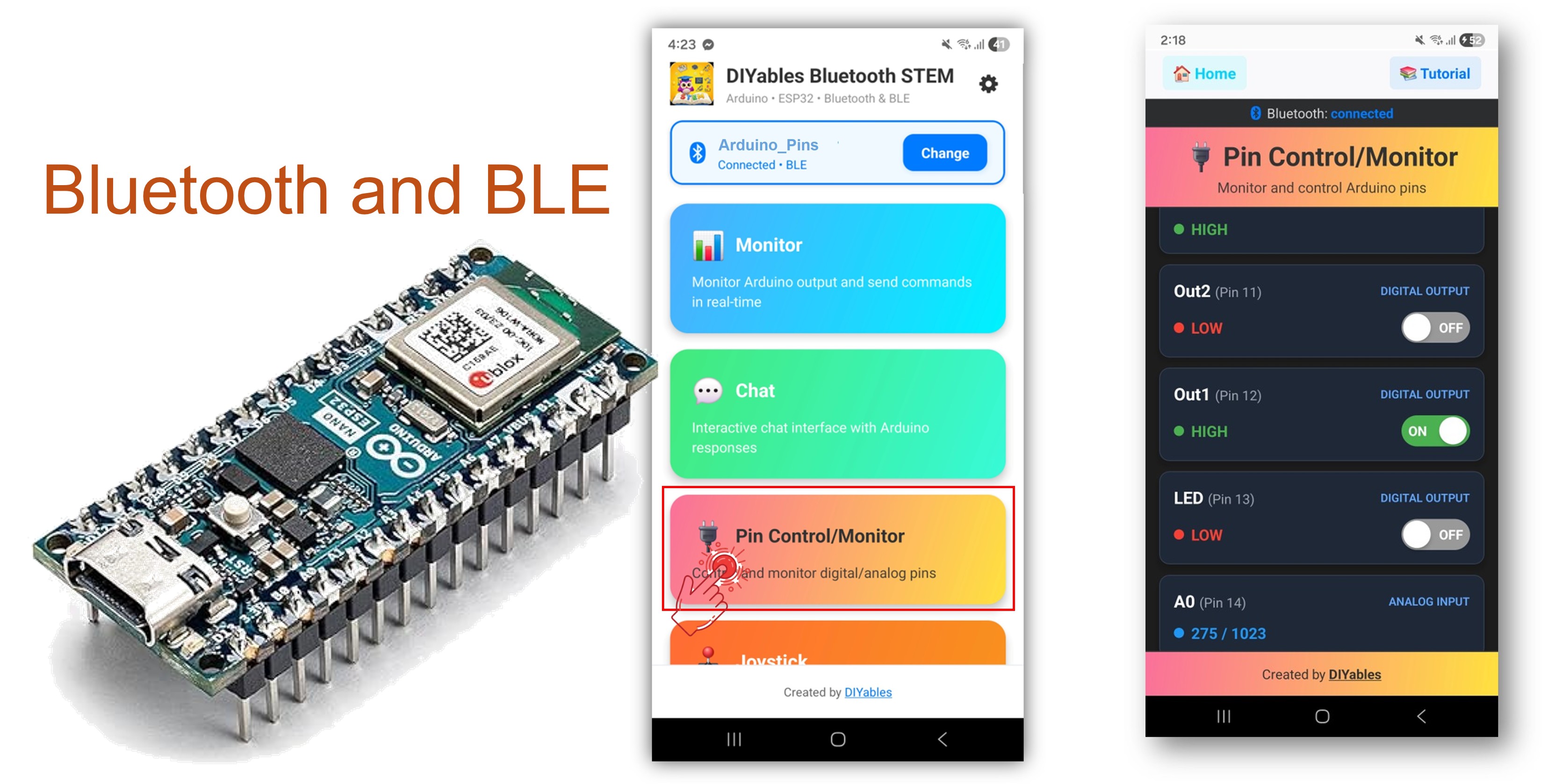
이 예제는 DIYables Bluetooth STEM 앱을 통한 BLE(블루투스 로우 에너지)를 사용하여 Arduino Nano ESP32에 원격 GPIO 핀 제어 및 모니터링을 제공합니다. 스마트폰에서 출력 핀을 제어하고 입력 핀을 무선으로 모니터링하세요. 릴레이 제어, 버튼 모니터링, LED 전환, 원격 핀 접근이 필요한 모든 애플리케이션에 적합합니다.
참고: Arduino Nano ESP32는 BLE만 지원하며 클래식 블루투스는 지원하지 않습니다. DIYables 블루투스 앱은 BLE를 통해 Android와 iOS 모두에서 작동합니다.
기능
- 출력 제어: 디지털 핀을 원격으로 HIGH 또는 LOW 설정
- 입력 모니터링: 디지털 및 아날로그 핀 상태 읽기
- 핀 이름 지정: 각 핀에 설명적인 레이블 지정 (예: "LED", "Relay")
- 실시간 업데이트: 핀 상태 변경을 앱으로 푸시
- 최대 16개 핀: 여러 핀을 동시에 제어
- Android 및 iOS 지원: BLE는 두 플랫폼 모두 호환
- 페어링 불필요: BLE는 수동 페어링 없이 연결
필요한 하드웨어
| 1 | × | 아두이노 나노 ESP32 | 쿠팡 | 아마존 | |
| 1 | × | USB 케이블 타입-A to 타입-C (USB-A PC용) | 쿠팡 | 아마존 | |
| 1 | × | USB 케이블 타입-C to 타입-C (USB-C PC용) | 아마존 | |
| 1 | × | 브레드보드 | 쿠팡 | 아마존 | |
| 1 | × | 점퍼케이블 | 쿠팡 | 아마존 | |
| 1 | × | (추천) 아두이노 나노용 스크루 터미널 확장 보드 | 쿠팡 | 아마존 | |
| 1 | × | (추천) 아두이노 나노용 브레이크아웃 확장 보드 | 쿠팡 | 아마존 | |
| 1 | × | (추천) 아두이노 나노 ESP32용 전원 분배기 | 쿠팡 | 아마존 |
공개: 이 포스팅 에 제공된 일부 링크는 아마존 제휴 링크입니다. 이 포스팅은 쿠팡 파트너스 활동의 일환으로, 이에 따른 일정액의 수수료를 제공받습니다.
Arduino Nano ESP32 코드
빠른 시작
- Arduino Nano ESP32가 처음이신가요? 아두이노 나노 ESP32 - 소프트웨어 설치를 참조하세요.
- USB로 Arduino Nano ESP32를 컴퓨터에 연결하세요.
- Arduino IDE를 열어주세요.
- Arduino Nano ESP32 보드와 올바른 COM 포트를 선택하세요.
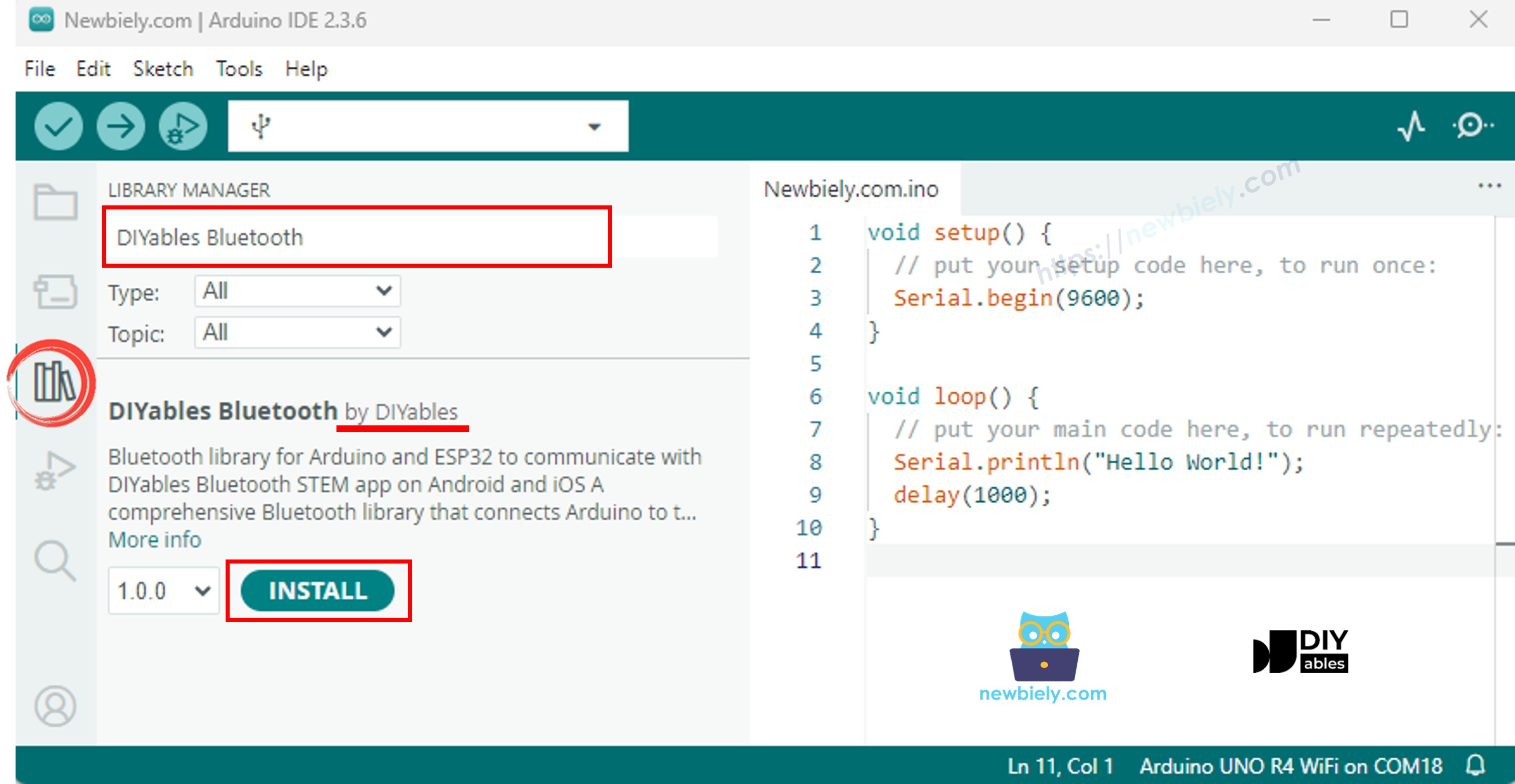
- 왼쪽 사이드바에서 라이브러리 아이콘을 클릭하세요.
- "DIYables Bluetooth"를 검색하고 DIYables의 DIYables Bluetooth 라이브러리를 선택하세요.
- 설치를 클릭하세요.
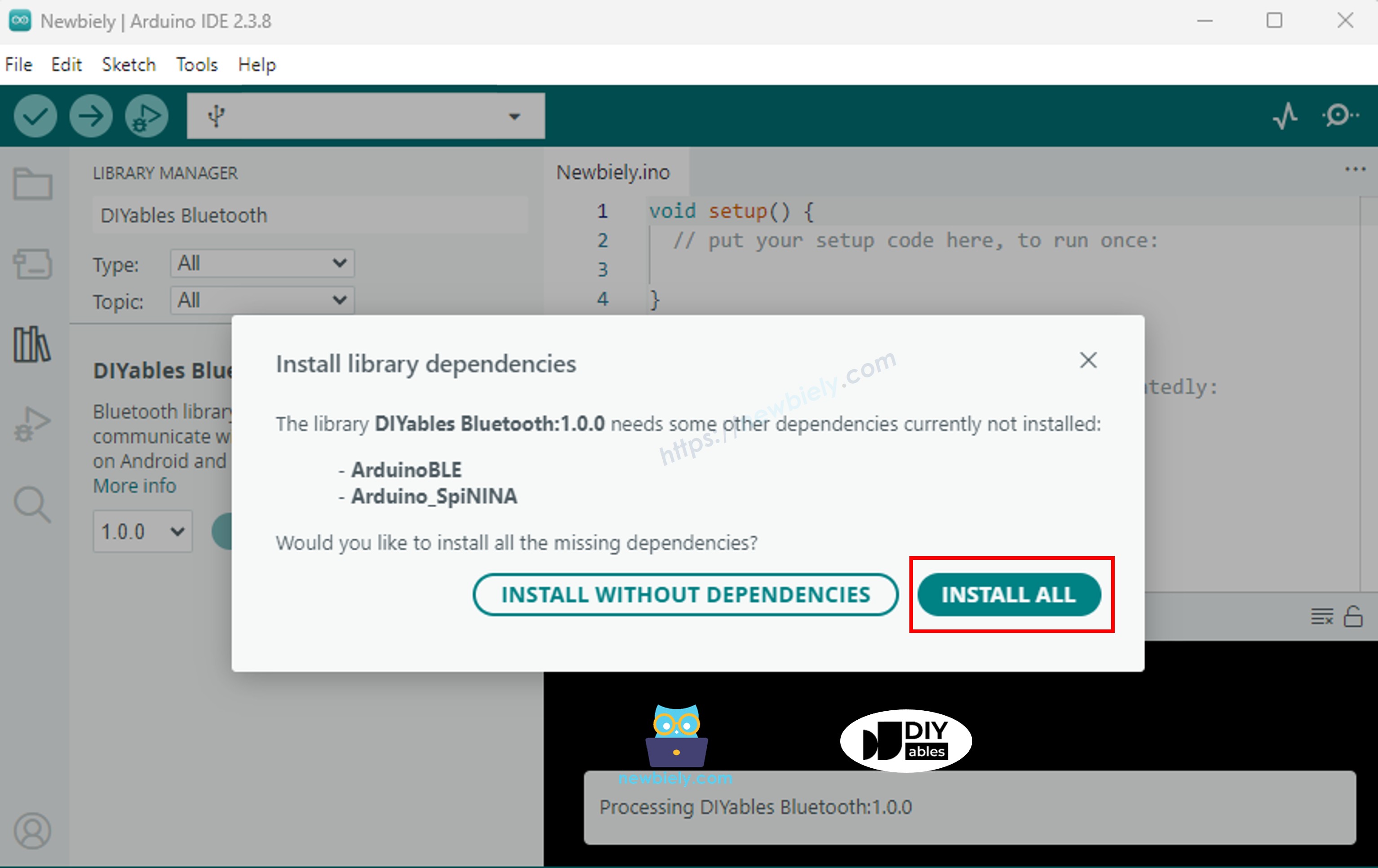
- 종속성 설치 메시지가 나타나면 모두 설치를 클릭하세요.
BLE 코드
- Arduino IDE에서 파일 예제 DIYables Bluetooth ArduinoBLE_PinControl을 열거나, 코드를 편집기에 붙여 넣으세요.
/*
* DIYables Bluetooth Library - ESP32 BLE Pin Control/Monitor Example
* Works with DIYables Bluetooth STEM app on Android and iOS
*
* This example demonstrates the Bluetooth Pin Control/Monitor feature:
* - Control digital output pins via Bluetooth
* - Monitor digital input pins
* - Monitor analog input pins
* - Configure pin modes (INPUT/OUTPUT)
*
* Tutorial: https://diyables.io/bluetooth-app
* Author: DIYables
*/
#include <DIYables_BluetoothServer.h>
#include <DIYables_BluetoothPinControl.h>
#include <platforms/DIYables_Esp32BLE.h>
// BLE Configuration
const char* DEVICE_NAME = "ESP32BLE_Pins";
const char* SERVICE_UUID = "19B10000-E8F2-537E-4F6C-D104768A1214";
const char* TX_UUID = "19B10001-E8F2-537E-4F6C-D104768A1214";
const char* RX_UUID = "19B10002-E8F2-537E-4F6C-D104768A1214";
// Create Bluetooth instances
DIYables_Esp32BLE bluetooth(DEVICE_NAME, SERVICE_UUID, TX_UUID, RX_UUID);
DIYables_BluetoothServer bluetoothServer(bluetooth);
// Create Pin Control/Monitor app instance
DIYables_BluetoothPinControl bluetoothPins;
// Pin configuration (ESP32 GPIOs)
const int LED_PIN = LED_BUILTIN; // Built-in LED
const int OUTPUT_PIN_1 = D6;
const int OUTPUT_PIN_2 = D7;
const int INPUT_PIN_1 = D4;
const int INPUT_PIN_2 = D5;
const int ANALOG_PIN_1 = A0; // Input-only ADC pin
const int ANALOG_PIN_2 = A1; // Input-only ADC pin
void setup() {
Serial.begin(115200);
delay(1000);
Serial.println("DIYables Bluetooth - ESP32 BLE Pin Control/Monitor Example");
// Initialize pins
pinMode(LED_PIN, OUTPUT);
pinMode(OUTPUT_PIN_1, OUTPUT);
pinMode(OUTPUT_PIN_2, OUTPUT);
pinMode(INPUT_PIN_1, INPUT_PULLUP);
pinMode(INPUT_PIN_2, INPUT_PULLUP);
// Initialize Bluetooth server with platform-specific implementation
bluetoothServer.begin();
// Add digital pins app to server
bluetoothServer.addApp(&bluetoothPins);
// Configure which pins are accessible via Bluetooth with custom names
bluetoothPins.enablePin(LED_PIN, BT_PIN_OUTPUT, "LED");
bluetoothPins.enablePin(OUTPUT_PIN_1, BT_PIN_OUTPUT, "Out1");
bluetoothPins.enablePin(OUTPUT_PIN_2, BT_PIN_OUTPUT, "Out2");
bluetoothPins.enablePin(INPUT_PIN_1, BT_PIN_INPUT, "Btn1");
bluetoothPins.enablePin(INPUT_PIN_2, BT_PIN_INPUT, "Btn2");
bluetoothPins.enablePin(ANALOG_PIN_1, BT_PIN_INPUT, "A34");
bluetoothPins.enablePin(ANALOG_PIN_2, BT_PIN_INPUT, "A35");
// Set up connection event callbacks
bluetoothServer.setOnConnected([]() {
Serial.println("Bluetooth connected!");
});
bluetoothServer.setOnDisconnected([]() {
Serial.println("Bluetooth disconnected!");
});
// Set up callback for pin write commands
bluetoothPins.onPinWrite([](int pin, int state) {
digitalWrite(pin, state);
Serial.print("Pin ");
Serial.print(pin);
Serial.print(" set to ");
Serial.println(state ? "HIGH" : "LOW");
});
// Set up callback for pin read commands
bluetoothPins.onPinRead([](int pin) -> int {
int state;
if (pin == ANALOG_PIN_1 || pin == ANALOG_PIN_2) {
state = analogRead(pin);
Serial.print("Analog pin ");
Serial.print(pin);
Serial.print(" read: ");
Serial.println(state);
} else {
state = digitalRead(pin);
Serial.print("Digital pin ");
Serial.print(pin);
Serial.print(" read: ");
Serial.println(state ? "HIGH" : "LOW");
}
return state;
});
// Set up callback for pin mode changes
bluetoothPins.onPinModeChange([](int pin, int mode) {
pinMode(pin, mode == BT_PIN_OUTPUT ? OUTPUT : INPUT_PULLUP);
Serial.print("Pin ");
Serial.print(pin);
Serial.print(" mode changed to ");
Serial.println(mode == BT_PIN_OUTPUT ? "OUTPUT" : "INPUT");
});
Serial.println("Waiting for Bluetooth connection...");
Serial.print("Enabled pins: ");
Serial.println(bluetoothPins.getEnabledPinCount());
}
void loop() {
bluetoothServer.loop();
static unsigned long lastInputCheck = 0;
static int lastInputState1 = HIGH;
static int lastInputState2 = HIGH;
static int lastAnalogState1 = 0;
static int lastAnalogState2 = 0;
if (millis() - lastInputCheck >= 100) {
lastInputCheck = millis();
int currentState1 = digitalRead(INPUT_PIN_1);
if (currentState1 != lastInputState1) {
lastInputState1 = currentState1;
bluetoothPins.updatePinState(INPUT_PIN_1, currentState1);
Serial.print("Input pin ");
Serial.print(INPUT_PIN_1);
Serial.print(" changed to ");
Serial.println(currentState1 ? "HIGH" : "LOW");
}
int currentState2 = digitalRead(INPUT_PIN_2);
if (currentState2 != lastInputState2) {
lastInputState2 = currentState2;
bluetoothPins.updatePinState(INPUT_PIN_2, currentState2);
Serial.print("Input pin ");
Serial.print(INPUT_PIN_2);
Serial.print(" changed to ");
Serial.println(currentState2 ? "HIGH" : "LOW");
}
// ESP32 has 12-bit ADC (0-4095)
int currentAnalog1 = analogRead(ANALOG_PIN_1);
if (abs(currentAnalog1 - lastAnalogState1) > 40) { // ~1% of 4095
lastAnalogState1 = currentAnalog1;
bluetoothPins.updatePinState(ANALOG_PIN_1, currentAnalog1);
Serial.print("Analog pin ");
Serial.print(ANALOG_PIN_1);
Serial.print(" changed to ");
Serial.println(currentAnalog1);
}
int currentAnalog2 = analogRead(ANALOG_PIN_2);
if (abs(currentAnalog2 - lastAnalogState2) > 40) {
lastAnalogState2 = currentAnalog2;
bluetoothPins.updatePinState(ANALOG_PIN_2, currentAnalog2);
Serial.print("Analog pin ");
Serial.print(ANALOG_PIN_2);
Serial.print(" changed to ");
Serial.println(currentAnalog2);
}
}
delay(10);
}
- 업로드를 클릭하여 스케치를 보드에 플래시하세요.
- 시리얼 모니터를 열어주세요.
- 시리얼 모니터 출력은 다음과 같아야 합니다:
8
Serial.println("Hello World!");
Message (Enter to send message to 'Arduino Nano ESP32' on 'COM15')
New Line
9600 baud
DIYables Bluetooth - Pin Control/Monitor Example
Waiting for Bluetooth connection...
Enabled pins: 7
모바일 앱
참고: DIYables 블루투스 앱은 BLE를 통해 Android와 iOS 모두에서 작동합니다. 수동 페어링이 필요 없습니다.
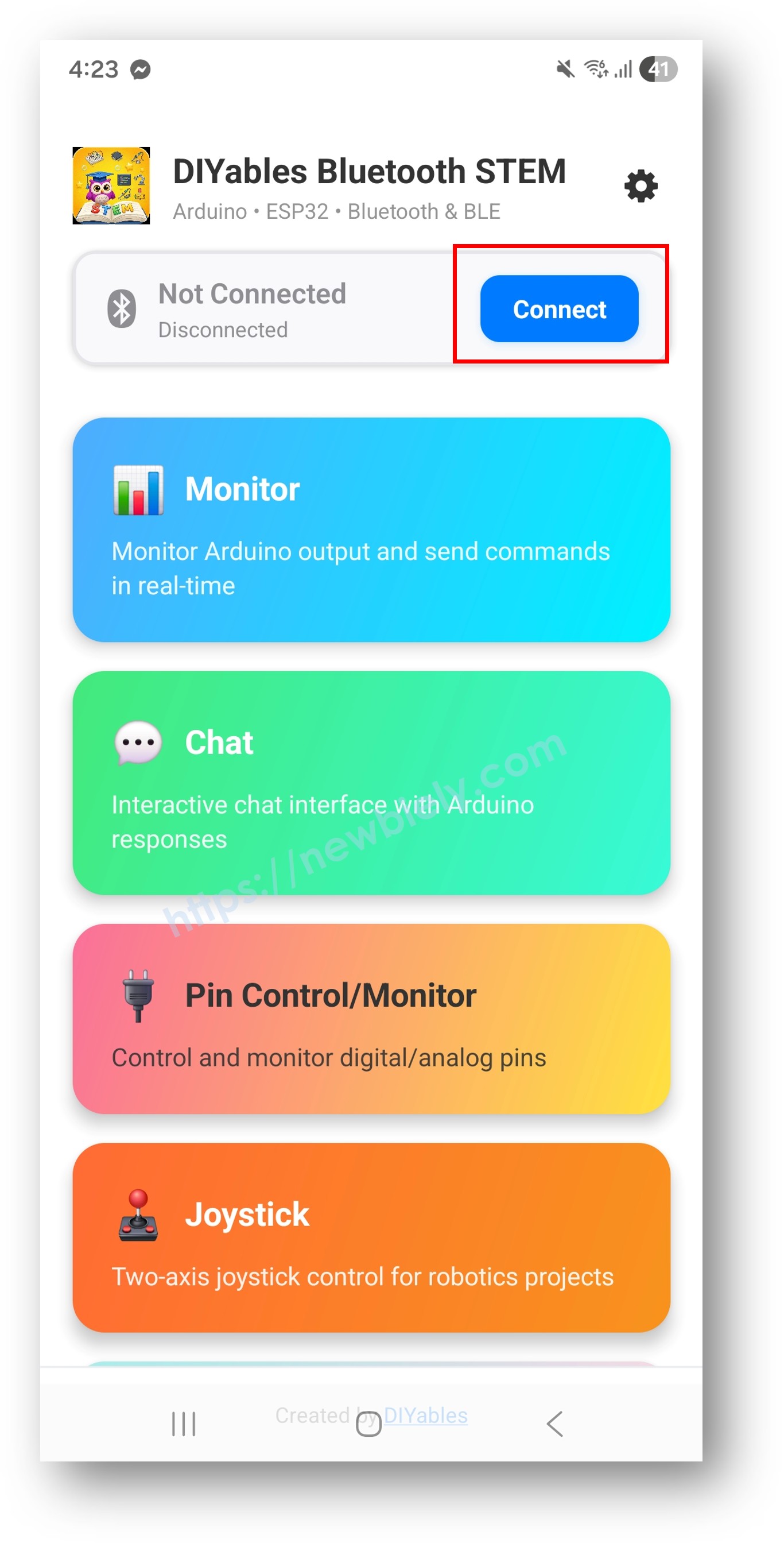
- DIYables 블루투스 앱을 실행하세요.
- 처음 실행 시 다음 권한을 허용하세요:
- 근처 기기 (Android 12+) / 블루투스 (iOS) — 블루투스 기기 스캔 및 연결에 필요
- 위치 (Android 11 이하에만 해당) — 구형 Android 버전에서 BLE 스캔에 필요
- 기기에서 블루투스가 활성화되어 있는지 확인하세요.
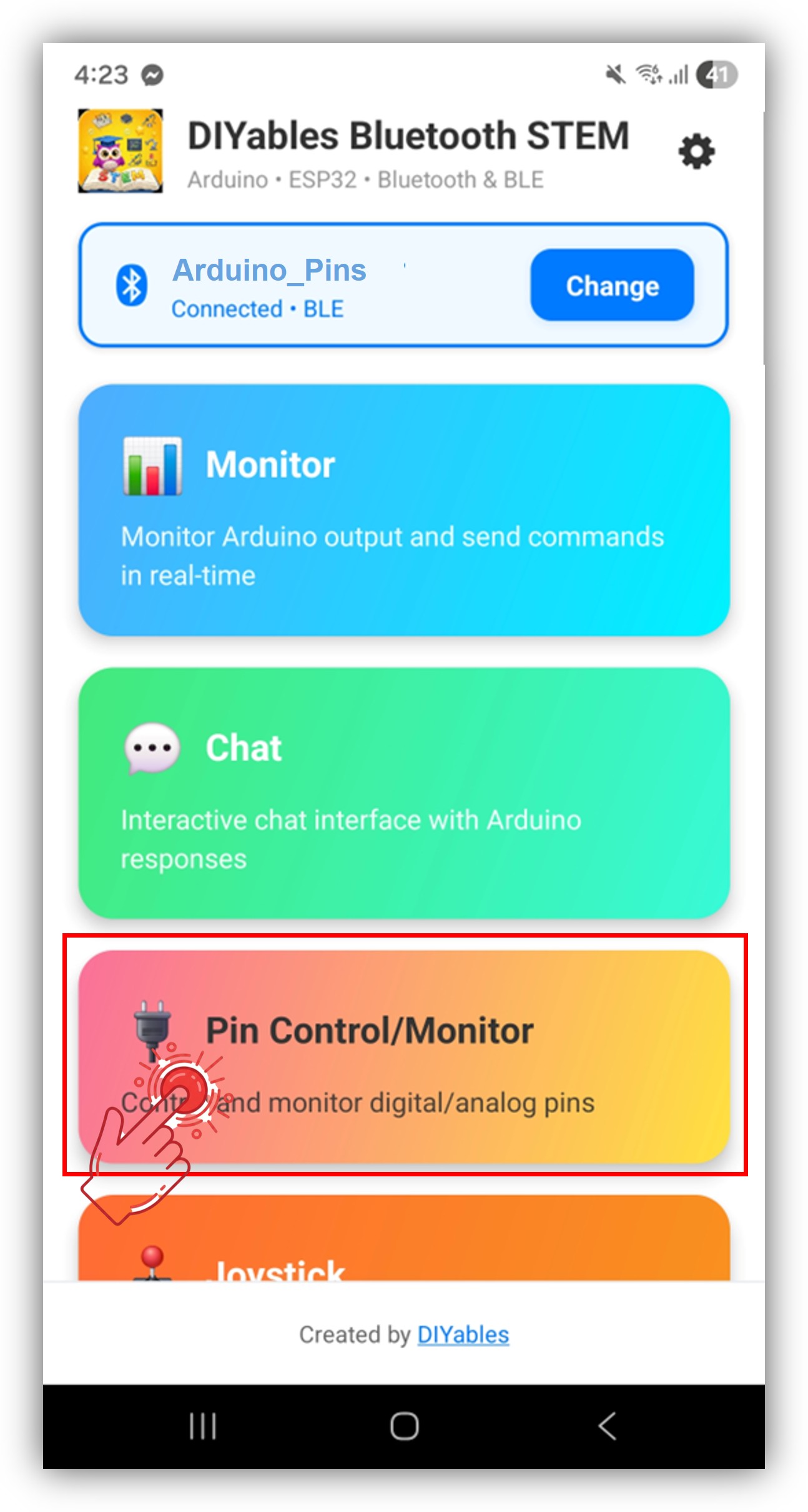
- 홈 화면에서 연결을 탭하세요. 앱이 BLE 기기를 스캔합니다.
- 스캔 결과에서 "Arduino_Pins"를 탭하세요.
- 연결 후 홈 화면으로 돌아가 디지털 핀 앱을 여세요.
홈 화면의 설정 아이콘을 탭하여 앱을 표시하거나 숨길 수 있습니다. 자세한 내용은 DIYables 블루투스 앱 사용 설명서를 참조하세요.
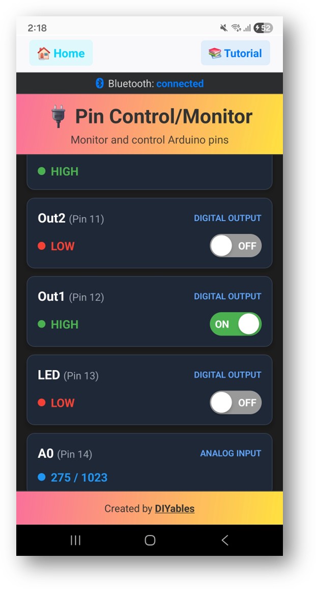
- 활성화된 핀이 이름 및 현재 상태와 함께 나열됩니다.
- 출력 핀을 탭하여 HIGH/LOW로 전환하고, 입력 핀 값이 실시간으로 업데이트되는 것을 확인하세요.
Arduino IDE의 시리얼 모니터를 다시 확인하면 다음과 같이 표시됩니다:
8
Serial.println("Hello World!");
Message (Enter to send message to 'Arduino Nano ESP32' on 'COM15')
New Line
9600 baud
Bluetooth connected!
Pin 13 set to HIGH
Pin 13 set to LOW
Digital pin 7 read: HIGH
창의적인 커스터마이징 - 프로젝트에 코드 적용하기
핀 활성화
// Enable pins with mode and friendly name
bluetoothPins.enablePin(13, BT_PIN_OUTPUT, "LED");
bluetoothPins.enablePin(12, BT_PIN_OUTPUT, "Relay");
bluetoothPins.enablePin(7, BT_PIN_INPUT, "Button");
bluetoothPins.enablePin(A0, BT_PIN_INPUT, "Sensor");
// Check enabled pin count
int count = bluetoothPins.getEnabledPinCount();
핀 쓰기/읽기/모드 처리
bluetoothPins.onPinWrite([](int pin, int state) {
digitalWrite(pin, state);
Serial.print("Pin ");
Serial.print(pin);
Serial.println(state ? " ? HIGH" : " ? LOW");
});
bluetoothPins.onPinRead([](int pin) -> int {
if (pin >= A0) {
return analogRead(pin);
}
return digitalRead(pin);
});
bluetoothPins.onPinModeChange([](int pin, int mode) {
pinMode(pin, mode == BT_PIN_OUTPUT ? OUTPUT : INPUT_PULLUP);
});
상태 변경 푸시
// Notify the app when a pin state changes
bluetoothPins.updatePinState(7, digitalRead(7));
bluetoothPins.updatePinState(A0, analogRead(A0));
프로그래밍 예제
버튼 모니터와 함께 릴레이 제어
const int RELAY_PIN = 12;
const int BUTTON_PIN = 7;
void setup() {
pinMode(RELAY_PIN, OUTPUT);
pinMode(BUTTON_PIN, INPUT_PULLUP);
bluetoothPins.enablePin(RELAY_PIN, BT_PIN_OUTPUT, "Relay");
bluetoothPins.enablePin(BUTTON_PIN, BT_PIN_INPUT, "Button");
bluetoothPins.onPinWrite([](int pin, int state) {
digitalWrite(pin, state);
});
}
void loop() {
bluetoothServer.loop();
// Monitor button and push changes
static int lastState = HIGH;
int state = digitalRead(BUTTON_PIN);
if (state != lastState) {
lastState = state;
bluetoothPins.updatePinState(BUTTON_PIN, state);
}
delay(10);
}
다중 LED 컨트롤러
const int LED_PINS[] = {8, 9, 10, 11, 12, 13};
const char* LED_NAMES[] = {"Red", "Green", "Blue", "Yellow", "White", "Built-in"};
const int NUM_LEDS = 6;
void setup() {
for (int i = 0; i < NUM_LEDS; i++) {
pinMode(LED_PINS[i], OUTPUT);
bluetoothPins.enablePin(LED_PINS[i], BT_PIN_OUTPUT, LED_NAMES[i]);
}
bluetoothPins.onPinWrite([](int pin, int state) {
digitalWrite(pin, state);
});
}
문제 해결
일반적인 문제
1. 앱에서 기기가 보이지 않음
- 보드에 전원이 공급되고 스케치가 업로드되었는지 확인하세요
- 스마트폰에서 블루투스가 활성화되어 있는지 확인하세요
- Android 11 이하에서는 위치 서비스도 활성화하세요
2. 핀 전환이 작동하지 않음
- 핀이 BT_PIN_OUTPUT 모드로 활성화되어 있는지 확인하세요
- onPinWrite 콜백이 등록되어 있는지 확인하세요
- 배선 연결을 확인하세요
3. 입력 핀이 업데이트되지 않음
- 핀 상태가 변경될 때 updatePinState()가 호출되는지 확인하세요
- 루프의 폴링 빈도를 확인하세요
4. 아날로그 값이 표시되지 않음
- 아날로그 핀에 대해 onPinRead 콜백에서 analogRead()를 사용하세요
- 아날로그 핀은 0–1023 범위의 값을 반환합니다
5. 연결이 자주 끊김
- 아두이노와의 거리를 줄이세요
- 안정적인 USB 전원 공급을 확보하세요
6. 업로드 실패 또는 보드 인식 불가
- 보드 매니저를 통해 최신 Arduino Nano ESP32 보드 패키지를 설치하세요
- 다른 USB 케이블이나 포트를 시도해 보세요
프로젝트 아이디어
- 다중 릴레이 제어 패널
- 버튼 및 스위치 모니터
- LED 조명 컨트롤러
- 홈 자동화 스위치 패널
- 센서 입력 대시보드
다음 단계
블루투스 디지털 핀 예제를 완료한 후 다음을 살펴보세요:
- 블루투스 슬라이더 — 아날로그 값 제어
- 블루투스 모니터 — 텍스트 기반 상태 피드백
- 블루투스 테이블 — 구조화된 핀 상태 표시
- 블루투스 다중 앱 — 핀 제어와 다른 앱 위젯 결합


